Do you have a question about the Global garden products 63 and is the answer not in the manual?
Explanation of symbols used for warnings, references, and specific working methods within the manual.
Details on the machine's identification label, model, and serial number for repair requests and parts ordering.
Information on the motor's technical specifications and serial number for requesting spare parts.
Details on guarantee terms and conditions, including specific conditions for the engine.
Requirements for service centers to create repair reports, including serial number and parts used.
Manufacturer's process for receiving and acting upon recurring fault notifications.
Procedure for requesting spare parts, emphasizing the need for code numbers and identification details.
Specifies that maintenance must be done by expert mechanics familiar with safety regulations.
Details checks for safety devices, covers, and labels to maintain machine safety standards.
Recommendations for safe servicing, including disconnecting power, using gloves, and avoiding hazards.
Information on standard tools and any special equipment required for operations.
Defines symbols and terms used to highlight critical safety information and warnings.
Lists standard workshop tools and specific special tools required for various procedures.
Instructions for safely lifting the machine from the front using a jack and wooden block.
Instructions for safely lifting the machine from the rear, including securing wheels.
Detailed steps for safely positioning the machine vertically for easier access to lower parts.
Guidance on the correct orientation and fitting of 'Benzing' snap rings for secure attachment.
Instructions for adjusting joint pivot pins to ensure free rotational movement without excessive play.
Advice on replacing damaged crown fasteners, emphasizing proper insertion and tool usage.
Describes tuning the machine whenever possible as part of maintaining optimal performance.
Recommending a maintenance program to customers for prearranged intervals.
Checklist of checks for occasional tuning, including safety devices, filters, oil, and blade.
List of tasks for routine maintenance, encompassing items from occasional tuning plus battery, belts, and lubrication.
Procedure to check the control lever mobility and perform blade engagement adjustment.
Adjusting the control cable adjuster to regain reduced braking capacity and checking for wear.
Adjusting the stretcher to correct forward drive issues potentially caused by belt length changes.
Adjusting the cutting deck to be parallel crosswise and slightly lower at the front.
Compensating for differences in height between the left and right sides of the deck.
Checking the exact toe-in by measuring the center distance of the connecting tie-rod.
Adjusting the tie-rod to ensure the steering wheel is straight when the machine travels straight.
Procedure to check blade alignment using a metal rod and measuring distances to the ends.
Steps for dismantling and reassembling the blade, including torque specifications for nuts and bolts.
Instructions for sharpening both cutting edges and checking blade balance for vibration reduction.
Identifies components like the fuel tank and steering gear accessible after removing the wheel cover.
Steps for removing the seat, steering wheel column, and related components.
Procedure for removing pedals, parking brake handle, and blade engagement lever.
Instructions for removing the cover by undoing self-threading screws at different locations.
Explains that removing the channel is necessary for brake and drive engagement adjustments.
Includes removing collector channel, wheel cover, and emptying fuel tank before deck removal.
Procedure for disconnecting the engine stop connector on electric start and manual start models.
Steps to remove the front mask and starter cable for manual start engines.
Procedure to release the spring from the drive engagement mechanism.
Instructions for detaching the cutting deck using three trace rods, noting its weight.
Reverse steps for refitting, checking joint pins, and performing necessary adjustments.
States that the engine can only be dismounted after removing the cutting deck and clutch.
Locating and undoing screws fastening the engine to the cutting deck, noting screw length variations.
Describes the transmission unit as comprising gear change, chain drive, differential, brake, and axle shaft.
Includes removing the collector channel, positioning blocks, and dismantling rear wheels.
Steps for disconnecting the gear change control rod and neutral signaller cables.
Reverse steps for refitting, advisories on tie-rod repositioning, and final tightening.
Specifies that tyre repairs after puncture must be done by a specialist.
Instructions for removing wheels using a snap ring and reassembling with grease and spacer washer.
Lists the recommended tyre pressures for the front and rear wheels.
Steps for removing force-splined bushes using a round bar and hammer.
Instructions for inserting new bushes using a mallet or pad, ensuring correct pin positioning.
Includes removing wheel cover and positioning machine vertically for better visibility.
Steps for unhooking the spring, lifting the column, and removing the pinion and ring gear shaft.
Checks for anti-friction washers, pin alignment, and ring gear shaft nut tightening.
Explains the clutch's dual function and when to replace the outer clutch element due to wear.
Steps for removing the guard, springs, brake bracket, and the entire clutch unit.
Checking the friction surface for good condition, wear, and minimum thickness, with replacement advice.
Positioning machine vertically, dismantling clutch, and removing pulley from engine shaft.
Steps to loosen pulleys, free the belt, and remove it using the stretcher's idle pulley.
Disconnecting the wire from the accelerator lever and the carburetor lever.
Connecting the wire to the engine terminal, ensuring correct 'STARTER' position.
Steps to loosen the adjusting nut, unhook the cable end from the control lever.
Removing the protection cover, releasing the spring, and pulling out the cable.
Loosening the adjuster and unhooking the control cable terminal from the lever.
Ensuring correct cable positioning to pass the tie-rod and fit the adjuster securely.
Loosening the adjusting nut and unhooking the spring from the stretcher lever.
Unhooking the cable end from the pedal and positioning it correctly for routing.
Includes removing rear wheel, engine housing, and disconnecting control cable.
Steps for unhooking springs, removing snap rings, and pulling out the caliper unit pins.
Undo nuts to reach pads, clean with solvent if oily, and check lever screw play.
Procedure refers to complete dismantling of gear change, chain, and differential, depending on operation type.
Steps for removing chain tightener, neutral signaller, gear change lever, and the gear change itself.
Procedure for unscrewing and pulling out supports, checking dust cover rings and spacers on assembly.
Steps to remove the brake caliper and chain tightener before unscrewing nuts securing the supports.
Steps for replacing the chain, checking pinion and ring gear wear, and advising replacement of related parts.
Removing the front mask and pulling out the cable terminal to free the starter cable.
Blocking the cable at the engine and pulling it out of the drive pulleys.
Diagnosing problems like poor starting, no starter motor action, and starter motor not stopping.
Diagnosing why the engine does not start, checking fuel flow and starter system.
Diagnosing 10A fuse blowing, engine start failures, and engine stopping during use for manual start models.
Table showing how safety devices affect starting in electric start models.
Table showing how safety devices affect operation while cutting in electric start models.
Table showing how safety devices affect starting in manual start models.
Table showing how safety devices affect operation while cutting in manual start models.
Procedure for checking microswitches (grass-catcher, seat, blade, neutral, parking) using an ohmmeter.
Method for bridging contacts to check the engine stop function.
Procedure for checking microswitches (grass-catcher, seat, blade, neutral, parking) using an ohmmeter for manual start.
Checking battery voltage at the terminal board with a voltmeter when the key is in the 'ON' position.
Testing the starter relay by bridging terminals to hear a click and checking starter motor engagement.
Bridging power contacts to check if the starter motor operates, indicating a fault in the relay if it doesn't.
Checking power supply to the electronic card by positioning a jumper and measuring voltage.
Ensuring correct connections, attached earth connections, charged battery, and unblown fuse before checking.
Measuring battery terminal voltage while engine runs to check regulator function and identify blown fuses.
Details on sealed 'dual' batteries, emphasizing no need to add water or open the cover.
Precautions for keeping the battery charged, recharging flat batteries promptly, and before/after storage.
Instructions for recharging, including not recharging damaged batteries and checking for overheating.
Importance of following exact assembly positions for correct microswitch function.
Adjusting the seat microswitch by changing cam position to ensure correct activation.
Schematic diagram showing electrical connections for electric start models.
List of specified tightening torques for fixing bolts on main parts.
Summary of the drive engagement adjustment procedure, including control positions and settings.
Summary of blade engagement and brake adjustment, showing controls and measurement settings.
Diagram and dimensions related to the main frame assembly.
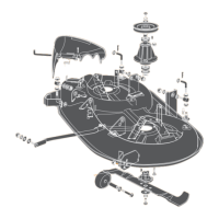
Diagram and dimensions related to the cutting deck assembly.
Diagram and dimensions related to steering geometry assembly.
Diagram and dimensions related to steering tie-rod assembly.
Diagram and dimensions related to gear lever rod assembly.
| Brand | Global garden products |
|---|---|
| Model | 63 |
| Category | Lawn Mower |
| Language | English |