EasyManua.ls Logo

Global Truss F34 - User Manual

Global Truss F34
4 pages
Print Icon
To Next Page IconTo Next Page
Loading...
GLOBAL TRUSS
MANUAL
We would like to thank you for choosing GLOBAL TRUSS trussing and ask for your own safety, to read and
follow these operating instructions carefully, before first start-up.
GENERAL
This trussing left our factory in perfect condition. If transport damages should be present, do not use this
product and contact your specialized dealer. To guarantee a safe practice, the safety and warning notes
listed in these operating instructions must be absolutely considered. Truss systems may only be built and
dismantled by qualified staff. The warranty claim expires with damage, which is caused by negl
ect of the
instructions. The manufacturer does not assume any liability for the damages resulting from it.
1. DRIFT
When rigging, dismantling, or servicing the trussing, make sure the area below installation place is blo
cked off.
Always fix lowered trusses with an appropriate safety-rope.
Unauthorized modifications on the trussing are forbidden due to safety reasons
1.1 ASSEMBLY
GLOBAL TRUSS products are designed user friendly and offer a convenient assembly. Nevertheless wor-
king with a truss construction requires a certain professional knowledge. Please do not attempt to work
with truss if you are unsure and lack knowledge; contact a rigging specialist for assistance.
1. Check the truss, the truss pins, the conical and the safety clips for any damages. If any piece is da
maged, do not use it and have it examined by a specialist or replace it with an original GLOBAL TRUSS
product.
2. Check that you have all parts.
a. 4-Point systems (e.g. F34) consist of 4 conical, 8 truss pins and 8 safety clips
b. 3-Point systems (e.g. F33) consist of 3 conical, 6 truss pins and 6 safety clips
c. 2-Point systems (e.g. F32) consist of 2 conical, 4 truss pins and 4 safety clips
www.dq.com.au
Question and Answer IconNeed help?

Do you have a question about the Global Truss F34 and is the answer not in the manual?

Summary

General Information and Safety

Drift Precautions

Safety measures during rigging, dismantling, and servicing, including area safety and preventing unauthorized modifications.

Assembly Guidelines

Instructions for user-friendly assembly of truss products, emphasizing professional knowledge and part checks.

Dismantling Procedures

Installation Standards

Overhead Rigging Requirements

Responsibilities and Compliance

Service and Maintenance

Overview

This document serves as a comprehensive manual for GLOBAL TRUSS trussing systems, providing essential information for safe and effective use, assembly, dismantling, installation, overhead rigging, and maintenance. It emphasizes the importance of adhering to safety guidelines and professional standards to prevent damage and ensure the longevity of the product.

Function Description

GLOBAL TRUSS trussing systems are designed to create robust and reliable support structures for various applications, particularly in event production, entertainment, and architectural installations. These systems are modular, allowing for flexible configurations to suit diverse needs. The primary function is to provide a stable framework capable of bearing significant loads, such as lighting, sound equipment, and decorative elements. The design prioritizes user-friendliness while maintaining high standards of structural integrity. The conical connection system, secured by truss pins and safety clips, ensures a strong and secure assembly. The manual also touches upon screwed GLOBAL TRUSS systems, indicating a broader range of connection methods depending on the specific product line.

Usage Features

The manual outlines several key usage features that contribute to the safe and efficient operation of GLOBAL TRUSS systems:

  • User-Friendly Assembly: GLOBAL TRUSS products are designed for convenient assembly, though professional knowledge is strongly recommended. The process involves inserting conical connectors into main tubes, aligning drillings, and securing them with truss pins and safety clips. The use of a copper or synthetic hammer is suggested for driving pins to ensure a tolerance-free connection.
  • Modular Design: The system's modularity allows users to connect multiple truss sections to create structures of varying sizes and complexities. This flexibility is crucial for adapting to different venue requirements and design specifications.
  • Clear Component Identification: The manual details the number of conical connectors, truss pins, and safety clips required for different point systems (e.g., 4-Point, 3-Point, 2-Point), simplifying the inventory check and assembly process.
  • Safety Mechanisms: Safety clips are a critical feature, designed to secure the truss pins and prevent them from falling out, thereby maintaining the structural integrity of the assembled truss.
  • Dismantling Procedure: The manual provides a clear, step-by-step guide for dismantling, which involves removing safety clips, pushing out truss pins, and separating truss sections. This ensures that the process is as straightforward and safe as assembly.
  • Installation Guidelines: Emphasizing compliance with DIN 15560 and national norms, the manual highlights the importance of a safe, stable, and non-dangerous ground surface for installation. It also mandates the use of secondary safety attachments, such as catch nets, to prevent any part of the primary installation from falling in case of failure.
  • Load Capacity and Stability: The installation must be constructed to hold 10 times the weight for one hour without harmful deformation, underscoring the robust design and safety margins of the trussing system.
  • Overhead Rigging Protocols: For overhead rigging, the manual stresses the need for extensive experience in load-capacity calculation, knowledge of installation materials, and regular safety inspections. It also specifies that the device must never swing freely and must be installed out of reach of people.
  • Safety Rope Requirement: When overhead rigging, the trussing must always be safeguarded with a safety rope, interpreted for at least 12 times the weight of the fixture, using only quick links with screw caps, and with a maximum drop distance of 20cm. Such ropes must not be reused after a single load due to fall or damage.
  • Responsibility of Users: The manual explicitly states that users are responsible for adhering to all local authority regulations, maintaining static regulations, and ensuring that any third parties involved in rigging receive copies of mounting instructions, official approvals, and load weight charts.
  • Authenticity of Parts: It is strongly recommended to use only original GLOBAL TRUSS products, identifiable by the engraved GLOBAL TRUSS Logo and TUV approval label, to ensure compatibility and safety.
  • Earthing Requirement: The truss construction must be properly earthed, a critical safety measure for electrical installations.

Maintenance Features

The manual outlines several key maintenance features and recommendations to ensure the continued safe and reliable operation of GLOBAL TRUSS systems:
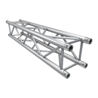
  • Pre-Use Inspection: Before first start-up and before each use, users are instructed to check the truss, truss pins, conical connectors, and safety clips for any damages. Any damaged parts must not be used and should either be examined by a specialist or replaced with original GLOBAL TRUSS products.
  • Regular Safety Inspections: Security and mechanical technological facilities must be checked by an expert at least once a year, before first start-up, after substantial modifications before restarting operation, and every four years for acceptance checking. Qualified personnel are responsible for carrying out these checks.
  • Screw Tightness and Corrosion Check: All screws in the construction must be tightly secured and free from corrosion. This is a critical point for maintaining structural integrity.
  • Deformation Check: Regular visual inspections are required to ensure that no deformations are visible on trusses, fastenings, support towers, or any other system components. Deformations can compromise the structural integrity and safety of the system.
  • Moving Parts Inspection: Mechanically moved parts should be checked to ensure they do not become unbalanced and do not show any wear or tear. This is particularly relevant for systems with dynamic components.
  • Electrical Cable Inspection: Any electrical connecting cables must be inspected for signs of damage, deposits, or material aging. Damaged cables can pose electrical hazards.
  • Exclusive Use of Original Spare Parts: To ensure compatibility, safety, and maintain the product's integrity, users are advised to use only original GLOBAL TRUSS spare parts for any replacements or repairs.
  • Post-Modification Re-testing: The characteristics of a structure made from GLOBAL TRUSS components can change with even the smallest modification. Therefore, any structure that undergoes changes must be re-tested as described in the manual.
  • Information Resources: The manual directs users to www.dq.com.au for truss datasheets, load tables, statics, and further information, providing a valuable resource for ongoing maintenance and operational planning. It also mentions a "GLOBAL TRUSS TOOL BOX APP" as an additional resource.

Global Truss F34 Specifications

General IconGeneral
TypeTruss
Outer Diameter Main Chord50 mm
Brace Diameter20 mm
MaterialAluminum
ColorAluminum
Load CapacityDepends on span and configuration
WeightVariable