Supplied By www.heating spares.co Tel. 0161 620 6677
20
220562A
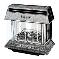
Diagram 8.5
8 F a u l t F i n d i n g
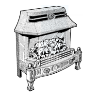
Diagram 8.4
9 R e p l a c e m e n t o f P a r t s
9.1 Burner
Disconnect the gas inlet pipe union nut, the electrode
assembly nut and the left hand burner mounting bracket
securing screw, see diagram 7.1.
Remove the burner wing nut, releasing the burner.
Remove the injector, burner alignment screw and burner
left hand mounting bracket, see diagram 7.1.
9.2 Injector
To remove the injector follow the instructions in
Section 7.6, paragraph 2.
9.3 Gas Tap and Micro Switch Assembly
Follow the instructions in Section 7.8 up to and
including paragraph 6.
Note: When replacing micro switch now follow
instructions in Section 7.8 up to and including
paragraph 7.
Make sure that the wiring harness strain relief is
correctly located into the slot secured by the locknut, see
diagram 7.3 and 7.4.
9.4 Electrode
Disconnect ignition lead from the electrode and remove
securing nut to release the electrode from the burner, see
diagram 7.3.
When replacing make sure that the spark gap is as shown
in diagram 7.3.
Notes
(a) Make sure the fire front is cold before replacing any
parts.
(b) Replacement of parts must be carried out by a
competent person.
(c) Remove the fire front castings as in Section 7.2.
(d) Remove the fuel bed, fuel effect bed base, fuel effect
pieces and insulation as in Section 7.3.
(e) BEFORE REMOVING OR REPLACING ANY
FIRE FRONT PART TURN THE GAS SERVICE
COCK TO “BACK BOILER ONLY ON”, see
diagram 3.2.
(f) ISOLATE THE ELECTRICAL SUPPLY TO THE
BACK BOILER.
(g) After replacing or disconnecting any gas carrying
component, always test for gas soundness, using a
suitable leak detection fluid and carry out functional
check of controls.
(h) To test the gas tap apply leak detection fluid to all
joints, light the burner and check all the joints for
leakage at all tap settings.
WARNING: Take care as the burner flame is fully
exposed.
(i) After removing or disconnecting any pipe work
always make sure that it is refitted correctly and
does not interfere with the fitting of the fire front.
(j) Unless stated otherwise reassembly of all parts is in
the reverse order to removal.
MICRO
SWITCH
ELECTRODE
BROWN
BROWN
EARTH
SPARK
GENERATOR
AV PP3 9V
ALKALINE
BATTERY
3177
3123
ELECTRODE
MICRO
SWITCH
SPARK GENERATOR
BROWN
BROWN
EARTH
 Loading...