Do you have a question about the Glow-worm Homeglow 2 BBU and is the answer not in the manual?
Crucial safety and operational advice for the fire. Covers safety device and potential causes for shutdown.
Warning regarding safe handling of sheet metal parts to prevent injury during installation or servicing.
Outlines legal and regulatory compliance for installation, including British Standards and Gas Safety Regulations.
Explains the appliance's compliance with EU directives for gas appliances and electrical equipment.
Provides essential specifications like gas connection, electrical input, weight, injectors, pressure, and heat input/output.
Details the specific back boiler units required and mounting considerations for the fire front.
Specifies minimum clearance distances around the fire front for safety and proper ventilation.
Specifies minimum hearth dimensions for installations that include a hearth.
Details requirements for fitting the fire front with a surround, including opening sizes and material finishing.
Covers direct wall fixing requirements, flatness, and clearances for installations without hearth or surround.
Explains how the fire front connects to the back boiler's flue collector assembly and ventilation needs.
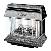
Step-by-step guide to safely unpack the fire front, check parts, and remove protective films.
Details how to attach the flue spigot assembly to the fire front casing.
Instructions for connecting the gas supply tube to the fire front, including cutting and deburring.
Guides the connection of the back boiler sensing tube to the air duct and its mounting bracket.
Specifies the source of the fire front's electrical supply and initial connection steps.
Detailed instructions for connecting the fire front's cable to the back boiler control box, including earthing and neutral connections.
Outlines essential electrical safety checks like insulation resistance, earth continuity, and polarity after installation.
Instructions on aligning the fire front spigot, marking fixing points, drilling, and securing the unit to the wall.
Details the final connections for gas supply and electrical plug/socket for the fire front.
Guides on safely lighting the appliance, checking the combustion products safety device, and initial operational checks.
Continuation of lighting procedures, gas soundness checks, and burner operation tests.
Instructions for installing internal parts like glass panels, insulation, and the coal effect assembly.
Further steps for installing internal components, focusing on fuel support grids and side cheeks.
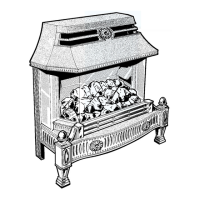
Detailed instructions for placing the coal effect pieces correctly onto the fire bed and rails.
Final steps for arranging the coal effect pieces, ensuring correct placement and gaps.
Explains the different tap positions and their corresponding flame effects and heat outputs.
Outlines how to perform a spillage test using a smoke match to check for proper combustion product ventilation.
Specific steps for conducting spillage tests when no fan is present in the room, with doors and windows closed.
Steps for spillage testing when a fan is present, detailing conditions for fan operation and room ventilation.
Instructions for refitting the outer casing, glass panel, hearth casting, and control plinth after servicing.
Further details on reassembling the fire front casing, securing screws, and fitting trim pieces.
Provides advice on safe use, cleaning trims, effects of heat on furnishings, and recommended servicing intervals.
General notes and safety precautions to be followed before and during servicing or parts replacement.
Steps for removing, cleaning, and refitting the front glass panel assembly.
Instructions for cleaning and maintaining the coal effect pieces, support grids, and glass base.
Details on disconnecting and servicing the burner assembly, injectors, and injector box.
Guidance on checking, cleaning, and replacing the combustion products discharge safety device and its components.
Instructions for removing, disconnecting, and fitting a replacement ignition lead.
Procedures for servicing the gas tap, piezo unit, and associated components like the filter.
Instructions on how to remove and replace the insulation within the appliance.
Steps for removing and refitting the glass base of the appliance.
Notes on bulb replacement for underbed lighting, including checking screw fitment.
Guidance on removing the old light switch and fitting a new one.
Details on accessing and replacing the small filter located in the pilot port of the gas tap.
Procedures for diagnosing and resolving problems related to the fire front's ignition system.
Steps for checking the mains electrical system, including earth continuity, polarity, and resistance.
A step-by-step flowchart to diagnose electrical faults in the appliance's wiring and components.
A flowchart to systematically troubleshoot issues preventing the fire front from igniting or burning correctly.
Instructions for testing the thermocouple using a multimeter and interrupter unit.
Explains potential issues indicated by the safety device's operation and related checks.
A diagnostic graph and procedure to assess the thermocouple circuit's performance and identify faults.
Provides a detailed table of all replaceable parts and guidance on how to order them.
An illustrated diagram showing the location and numbering of various replacement parts within the appliance.
General advice for fitting the fire front to existing Glow-worm back boiler units without a safety device.
Specific installation modifications required when the back boiler lacks a safety device, including electrical and sensing tube connections.
Detailed instructions for lighting the boiler and its pilot burner, including safety checks and troubleshooting.
Diagrams illustrating boiler controls, terminal blocks, and wiring connections for supplementary installations.
Details on adhesives, sealants, glass yarn, insulation, and ceramic fibre, with advice on handling and potential irritations.
| Brand | Glow-worm |
|---|---|
| Model | Homeglow 2 BBU |
| Category | Indoor Fireplace |
| Language | English |