Supplied By www.heating spares.co Tel. 0161 620 6677
5
221100C
2457
2468
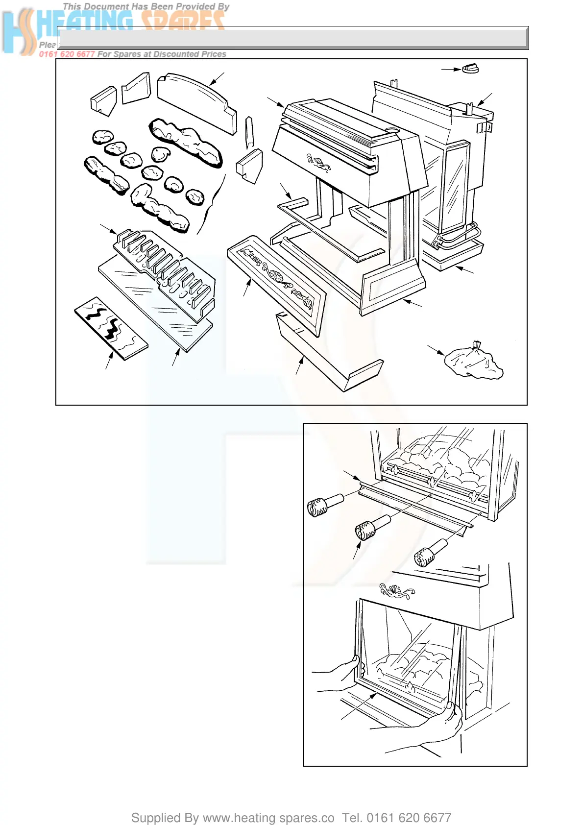
Diagram 3.2
PLINTH
CONTROL KNOB
COALS
TRIM
BODY
ASSEMBLY
INSULATION
FUEL
SUPPORT
GRID
Diagram 3.1
KNURLED
SCREW
(3 OFF)
FRONT
GLASS
PANEL
3.1 Unpacking
Remove the fire front flue spigot assembly.
Lift out the polystyrene tray which contains all the loose
parts, check these against diagram 3.1, also a loose items
pack, check contents against packed list.
Lift the outer carton clear to leave the fire front sitting on
the base tray.
The front glass panel must be removed before removal of
the fire front casing.
To remove the front glass panel release the three knurl
headed nuts and clamping plate, see diagram 3.2.
Place the glass panel aside until required.
To remove the casing release the two screws, as
diagram 6.26 tilt the casing forwards and lift it off,
leaving the fire front sitting in the base.
Note. Remove the black protective film from the canopy
trim, hearth trim and glass panel sides.
3 F i r e F r o n t P r e p a r a t i o n
CASING
HEARTH
CASTING
CASING
FLUE
SPIGOT
GLASS
BASE
COLOURED
GLASS
CLAMPING
PLATE
FIXING PACK INCLUSIVE
OF BACK BOILER
SENSING TUBE
 Loading...