Supplied By www.heating spares.co Tel. 0161 620 6677
11
221100C
6 L i g h t i n g a n d T e s t i n g a n d F i t t i n g I n t e r n a l P a r t s
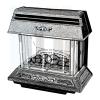
Diagram 6.6
2474
2471 2472
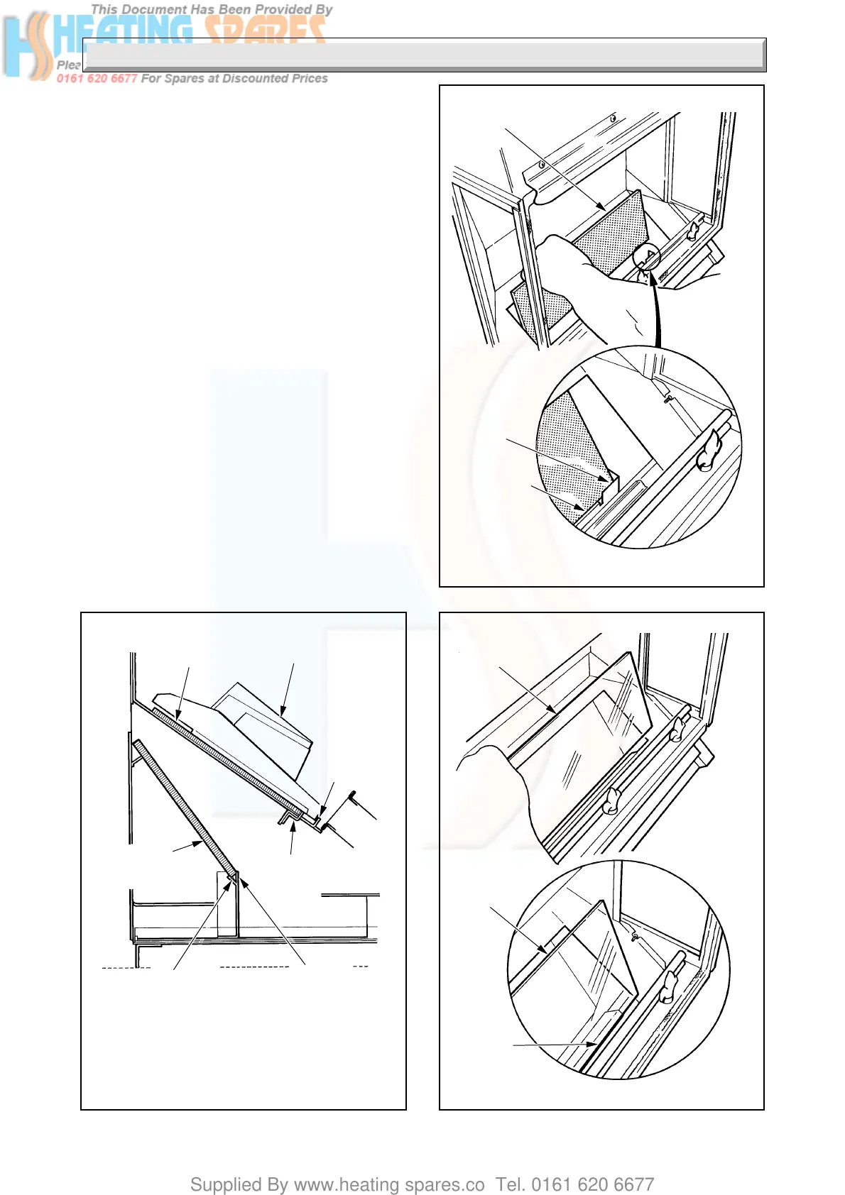
COLOURED
GLASS
BASE
GLASS
SUPPORT
ANGLE
VERTICAL
LUG
GLASS
SUPPORT
LUG
FUEL
SUPPORT
GRID LUG
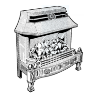
PLAIN GLASS
FUEL
SUPPORT
GRID
PLAIN
GLASS
BASE
GLASS
SUPPORT
ANGLE
Ensure glass base sits
on support angle
COLOURED
GLASS
PLAIN
GLASS
BASE
COLOURED
GLASS
SUPPORT
ANGLE
Ensure glass base sits
on support angle
Diagram 6.5
VERTICAL
LUG
6.2 Internal Parts - Fitting
CAUTION. If any of the glass panels, side and rear
insulation, support grid or coal effect pieces are damaged
do not light or further test the fire front before
replacement parts are fitted.
Remove the front glass panel, see diagram 3.2.
Check that the bulbs are screwed in, see diagram 8.9.
See diagram 8.10, operate switch to check that the lights
are working.
Follow the order given in diagram 6.4 to 6.22, to fit the
internal parts.
When replacing the front glass panel push it up into the
retaining angle, position the clamping plate and only
finger tighten the knurl headed nuts.
Diagram 6.4
 Loading...