Supplied By www.heating spares.co Tel. 0161 620 6677
3
220562A
Diagram 1.3
1 G e n e r a l
Any alteration that is not approved by Hepworth Heating
Ltd., could invalidate the B.S.I. Certification, the warranty
and could also infringe the current issue of the Statutory
Requirements, see Section 1.2.
C.E Mark
The CE mark on this appliance shows compliance with
Directive 90/396/EEC on the approximation of the Laws
of the Member States relating to appliances burning
gaseous fuels.
1.4 Data
Gas connection - from service cock
Weight - Total - 43kg in two packs
Injector - Bray 18/380
Burner pressure at
setting II - hot - 15.3mbar
- cold - 14.7mbar
Heat input - nominal - 5.28kW (18,000Btu/h)
Heat output - nominal - 1.40kW (4,780Btu/h)
Data label - at rear left hand side
of fire front
All dimensions, except as noted, are given in millimetres.
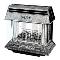
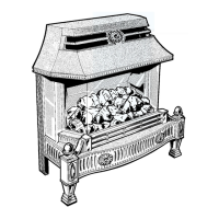
1.5 Fire Front Location
This fire front can only be fitted to a Glow-worm 45F,
45FR, 56F or 56FR back boiler unit which itself has been
installed in accordance with the Glow-worm Installation
and Servicing Instructions for the back boiler.
Before fitting the fire front it is important to make sure
that the annular space between the back boiler flue liner
and the chimney is sealed at the base and top of the
chimney, as shown in diagram 1.3.
The back boiler air duct acts as a support for the
combustion chamber assembly.
The fire front must be secured to a vertical fire fixing
wall face. This wall face may be a chimney breast or
surround having a minimum flat area as shown in
diagram 1.2.
The combustion chamber flue spigot assembly projects
into the the back boiler flue collector assembly.
The gas supply is taken from the back boiler gas service
cock.
The back boiler must be correctly positioned in the
builder’s opening as the fire front is located by
connection to it.
1.6 Clearances
Restrictions must not be placed around the assembled fire
front, see diagram 1.2.
A shelf or surround of a maximum depth of 150mm may
be fitted, provided clearances are as shown in diagram 1.2.
However, for every 25mm above the fire front the depth
of the shelf may be increased by 25mm.
Combustible furniture or materials must not be placed
closer than 1metre (39in) in front of the fire front.
4018
825
305
305
150
MAX SHELF DEPTH
100
25
25
INSTALLATION
CENTRE LINE
FLAT AREA
FIRE FIXING
FACE
PREPARED BOILER BASE
Diagram 1.2
SEALING AND
CLAMPING
PLATE
AIR SPACE
600 mm
150mm (6in) plug ofMineral Wool
or similar- support as required
3102
 Loading...