3 2 1
N L
cylinder
control
C˚
immersion
heater
C˚
230 V AC
3 kW
1
1
3
2
2
4 4
IMMERSION HEATER, ELECTRICAL CONNECTIONS
4 Installation
12557
4.10 Drain Valve
A drain valve has to be tted in the cold water mains supply
between the Glow-worm cylinder and the cold water control
valves as low as possible, see diagram 4.5.
We recommend to t a hose pipe in the outlet of the drain
valve approximately 1 metre below the bottom of the cylinder
(this can be achieved by connecting a suction hose to the
outlet of the drain valve).
4.11 Electrical connections and controls
All electrical connections conform to BS 7671.
NOTE: The position of the discharge pipes (tundish), drain
valves and motorised valves etc. shall be positioned away
from any electrical components.
4.12 Immersion Heater
WARNING: The immersion heater must be earthed.
IMPORTANT: The immersion heater incorporates an energy
cut-off device and must not under any circumstances be
replaced by a standard immersion heater.
Only a correct genuine Glow-worm spare part is permitted.
The Glow-worm 115 - 300 cylinders are equipped with a
factory tted immersion heater.
All internal wiring is factory tted.
Install a separate electrical supply to the immersion heater in
accordance with the current IEE wiring regulations (BS 7671).
The immersion heater must be wired in 2.5 mm
2
heat-resisting
cable from a double pole isolating switch. The circuit must be
protected by a 13 amp fuse. The connection details for the
immersion heater are shown in diagram 4.8.
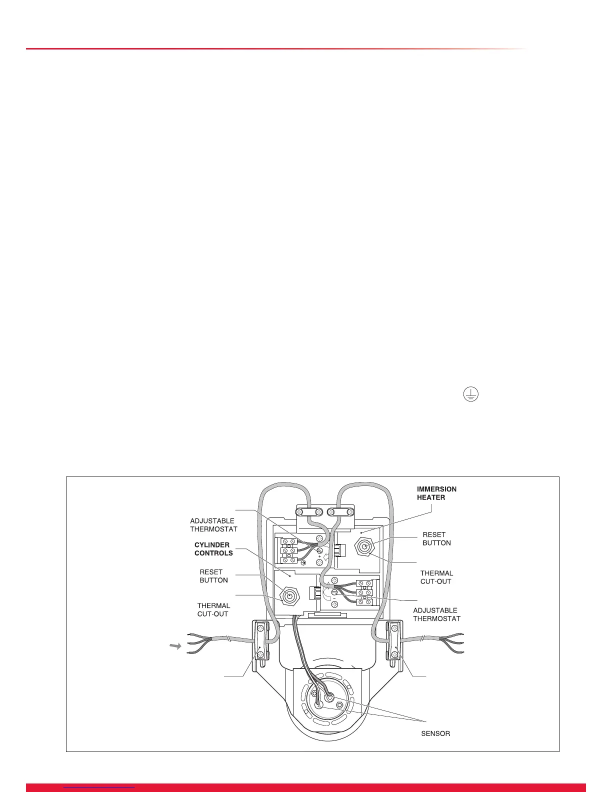
4.13 Electrical Connections and Controls
WARNING: The Glow-worm cylinder must be earthed.
The Glow-worm cylinder and accompanying boiler may be
controlled using various programmers and room thermostats,
details of which are given in section: Control Options.
The Glow-worm cylinder has a factory tted cylinder thermal
cut-out, thermostat and manual reset.
Diagram 4.8
IMPORTANT: Before resetting the thermal cutout or changing
the temperature setting of the thermostat, switch the electrical
supply off.
All internal wiring is factory tted.
The thermostat which controls the DHW temperature (see 1,
diagram 4.8) is adjustable between 20 and 65°C. The built in
safety thermal cut out operates at 90°C. Should the thermal
cut out be brought into operation, the motorized 2 port valve
will operated and shut the primary ow to the cylinder. Press
the reset button, see diagram 4.8 to reset thermal cut out and
motorised valve.
Connections to wiring centre
Remove the screw from the front panel.
Provide a wiring centre adjacent to the cylinder to make the
electrical connections.
Ensure that the cables are xed in the cord grip (see 4,
diagram 4.8).
Connect the Glow-worm boiler terminals to the corresponding
terminals of the wiring centre.
Connect the Glow-worm cylinder controls and the 2 port valve
ying lead to the terminals of the wiring centre.
Connect the terminals of the programmer and room
thermostat to the terminals of the wiring centre.
Connect a 3 amp fused mains supply to the terminals of the
wiring centre.
NOTE: All wiring must be carried out in accordance with
the current BS 7671 and the requirements for electrical
installations.
Check that the cylinder thermostat and immersion heater
sensors are correctly positioned in the tubes.
If you do not use the immersion heater then connect an
earth wire to the terminal marked
on the immersion
heater connector block.
13
 Loading...