Do you have a question about the Glowworm EASICOM 3 24c and is the answer not in the manual?
Defines intended use and required qualifications for safe product operation and maintenance.
Conveys crucial safety information to prevent death, injury, or damage.
Covers safety measures related to gas, flue gases, and electrical components.
Addresses risks from temperature, weight, substances, and water quality.
Advises on frost prevention and the importance of installing safety devices.
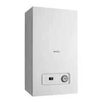
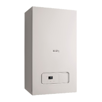
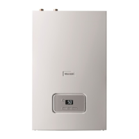
Lists general technical specifications for the EASICOM 3 24c and 28c models.
Provides detailed power, load, and heating specifications for both models.
Details specifications for domestic hot water and electrical components.
Explains CE marking and details information found on the product's data plate.
Describes the location of the serial number on the data plate and electronics box.
Identifies and illustrates the key functional components of the combi boiler.
Outlines the various safety devices integrated into the boiler system.
Describes the boiler's behavior and reset procedure during electrical supply interruptions.
Explains the built-in overheating protection and automatic shutdown mechanism.
Details the automatic frost protection mechanism that operates the pump below 12°C.
Explains how a blocked condensate drain affects boiler operation and how to resolve it.
Covers checking delivered components and product dimensions.
Specifies suitable installation locations and required minimum clearances.
Explains that compartment ventilation is not required.
Discusses flue outlet configurations, fall requirements, and terminal positioning regulations.
Details specific clearance dimensions for various installation sites of fan-supported flue terminals.
Details the horizontal concentric flue configuration.
Explains when and how to install a terminal guard for protection.
Details the vertical concentric flue configuration.
Describes the configuration for multiple boiler chimney flues.
Step-by-step guide for safely removing the front casing.
Provides a caution and procedure for removing a side section without causing damage.
Lists essential preparation steps before installing the boiler, including gas meter and pipework checks.
Advises on descaling the water to prevent scale deposition, especially with increased temperature.
Details the procedure for checking gas type compatibility and operating authorization.
Guides on applying heat insulation and connecting gas and water pipes correctly.
Explains how to connect the drain pipework ensuring visibility and safe routing.
Describes the preferred method for direct connection to an internal soil and vent stack.
Details direct connection to an external soil and vent stack.
Outlines the best practice for external termination to a gulley or hopper.
Details the process of installing and connecting the air/flue pipe system.
Provides instructions for accessing and closing the boiler's electronics box.
Illustrates the routing for the 24-V eBUS and 230 V cable routes.
Warns about incorrect wiring and damage to electronics, stressing correct terminal usage.
Explains how to use diagnostic codes to adapt the product to installation and customer requirements.
Step-by-step guide to activate diagnostic codes, including access codes.
Details how to select and set specific diagnostic codes for parameter adjustment.
Describes how to display the product's current operating mode using status codes.
Instructions on how to access and view the status codes.
Explains how to use check programmes for special functions and diagnostics.
Guide to initiating and navigating through various check programmes.
Shows how to view heating pressure and temperature readings during a check programme.
Outlines the initial start-up procedure, emphasizing the use of the benchmark checklist.
Provides essential guidance on checking and treating heating water quality to prevent damage.
Steps for checking heating water appearance, sediment, magnetite, and pH value.
Instructions for measuring and treating filling and supplementary water quality.
Detailed steps for correctly filling the condensate siphon.
Simple instruction to switch on the product via the main switch.
Advises on maintaining correct filling pressure and actions for low pressure conditions.
Instructions for flushing the heating system with cold water to remove contaminants.
Covers preliminary work and the process of filling and purging the heating installation.
Steps for filling the domestic hot water circuit and checking for leaks.
Details the procedure for checking and adjusting the gas setting by qualified personnel.
Instructions for checking flue gas installation integrity and recirculation.
Procedure for measuring and comparing the gas flow rate against specifications.
Guides on checking gas inlet working pressure and troubleshooting deviations.
Steps for measuring and verifying CO2 content at full load for correct combustion.
Instructions for flushing the heating system with hot water after it has reached operating temperature.
Procedures for checking the gas pipe, heating circuit, and hot water circuit for leaks.
How to check the heating mode operation and verify status codes.
How to check domestic hot water generation and verify status codes.
Details how to set the maximum burner anti-cycling time to prevent frequent burner cycling.
Instructions for adjusting the maximum burner anti-cycling time via diagnostic code d.02.
Procedure to reset the remaining burner anti-cycling time.
How to change the pump speed based on operating mode using diagnostic code d.19.
Guides on setting the bypass for optimal radiator performance or noise reduction.
Instructions for setting the domestic hot water temperature, including legionella prevention advice.
Instructs to complete the service record section of the Benchmark Checklist after servicing.
Emphasizes using only original seals when replacing components.
Advises adhering to minimum inspection and maintenance intervals.
Steps for checking and adjusting the CO2 content for optimal combustion.
Detailed procedure for setting the CO2 content using the adjustment screw.
Guides on removing the gas-air mixture unit, detailing its components.
General advice on rectifying faults, referring to fault codes and check programmes.
How to access and view the stored fault codes in the memory.
Procedure for deleting the fault memory using diagnostic code d.94.
How to reset all parameters to their factory default settings using diagnostic code d.96.
Steps to take before commencing repair work, including decommissioning.
Advice on using original spare parts for maintenance and repair.
Detailed instructions for replacing various defective components of the boiler.
Steps for removing the old burner and installing a new one.
Procedure for replacing the gas-air mixture unit.
Guides on removing and replacing the gas valve assembly.
Advises on correct packaging disposal and observing regulations.
A table detailing required inspection and maintenance tasks and their intervals.
| Type | Combi Boiler |
|---|---|
| Output Rating | 24 kW |
| Dimensions (HxWxD) | 700x390x280mm |
| Weight | 28.1 kg |
| Fuel Type | Natural Gas |
| Mounting | Wall Mounted |
| ERP Rating | A |
| CH Output | 24 kW |
| DHW Output | 24 kW |
| Warranty | 2 Years |