Article No. 28 100-
Version 12.2007
Page 2 of 12
IDENTIFICATION
Label
Explanation
Pursuant to EN 50081-1, EN 50082-1 and EN 61010-1 / A2
INSTALLATION
Check the indicator and the probe element for transport damages before start of the installation.
Indicator and measuring probe must only be installed and commissioned by qualified personnel.
This requirement also applies to maintenance and repairs. In case of improper installation, any
warranty claims will be forfeited.
• The device must only be installed into tanks which are not operated under pressure. This is to
say that the tanks must be equipped with a tank ventilation according to the regulations.
Additionally, heating oil and fuel tanks must have a functioning limit monitoring indicator as
overfill protection.
• The inlet of the probe cable at the tank must be sealed in such a way that no smell will permeate
or water will penetrate under operating conditions.
Notes on installation
Expert installation under observation of the technical regulations for planning, construction and
operation of the system as a whole is the precondition for faultless functioning of the contents
indicator. These regulations also include the accident prevention regulations of the employers’
liability insurance associations, the VDE regulations, and the installation and operating instructions
for the fluid tank. The housing of the indicator is suitable for wall mounting and is connected to the
230 V mains supply. Under normal circumstances, the indicator must be operated with the
housing cover closed. It is installed and commissioned by the qualified technician while the unit is
open.
➨ Warning: Keep away from the area of the 230V terminal.
Installation of the indicator
Mount the indicator to the wall in a suitable position. After loosening the four screws, open the
indicator by removing the cover. Mount the unit to a smooth vertical wall by means of four dowels.
Mount the housing of the indicator by the four fixing holes by means of the enclosed screws.
Take care not to damage the housing! After connecting the terminals and setting the unit up,
rescrew the cover.
The indicator must not be installed in areas subject to explosion hazards!
Installation of the probe element
• For welded basement steel tanks and buried tanks, the probe is installed by
means of the enclosed screw fitting with cable bushing.
• In most cases of installation to basement tanks, the fuel gauge with float used
before is dismounted so that its opening can be used to screw in the probe unit.
• With buried tanks, there usually is a free opening to screw in the probe element;
it will be closed with a removable filler plug.
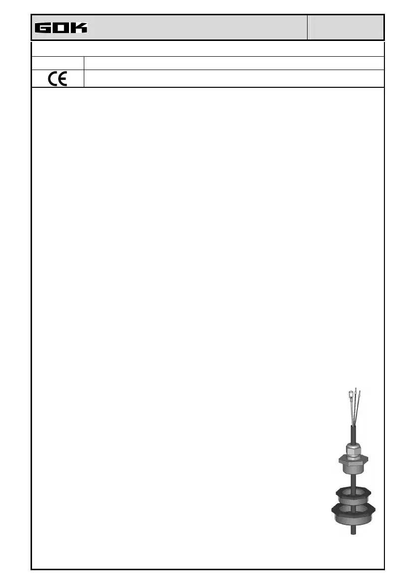
Installation of the probe into the tank by means of the enclosed screw fitting (see
illustration on the right):
• If applicable, switch the oil burner off and lock the take-off pipe of the tank.
• Clear the opening at the tank.
• Push the screw fitting, if applicable with reduction bush(es), over the probe
cable and insert the probe into the tank.
• Seal the screw fitting smell-tight (e.g. with PTFE tape) and screw it into the tank
cover.
• Lower the probe into the tank until the probe head touches the tank floor (you
will feel that through the cable). Then, screw down the cable gland to fix the
cable. Optionally, the probe can also be fixed in a lying position on the tank
floor.
• Usually, it is not necessary to perform a probe zero adjustment (step 9.Offset calibration).
 Loading...