Article No. 28 100-
Version 12.2007
Page 3 of 12
Re-open the take-off line of the tank and reactivate the oil burner if applicable. Check the function
of the oil burner.
Electrical Installation
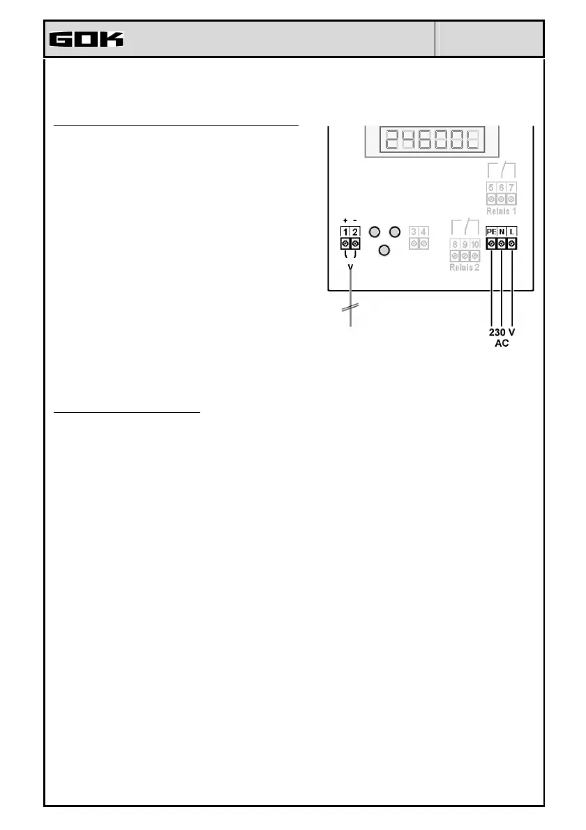
Indicator without cover lid
Connection probe cable
1 + = red
2 - = black
Connection line between indicator and probe unit:
Voltage: Probe element 20 V DC
Connection: Probe connection cable to terminals
1 + 2 (see Fig. on the right)
Air capillaries: The cable must be installed in such a
way that pressure equalization with the
ambient air is ensured but no moisture
can penetrate into the cable end.
Extension: The probe cable can be extended by
max. 200 m - e.g. with cable type NYM
or YR (moisture-proof) or NYY
(ground) and with min. cable cross-
section 2 x 0.4 mm2. For cable
extension in the dome or outdoors, a
watertight connection socket with
special pressure equalization filter
must be used (accessory).
Shield: If the probe cable (or extension) runs
close to power lines, a shielded signal
line should be used (connect shield to
PE terminal).
Connection of supply voltage:
Voltage: 230 V AC 50 Hz
Connection: Terminals PE, N + L to the indicator
(cable not comprised in the delivery )
Connection of the relay contacts at the indicator SmartBox 2 und SmartBox 3
The indicator SmartBox 2 has two relay contact pairs (SmartBox 3 ➜ one) for the connection of
external control circuits or for activating external alarm or signal devices.
In case of failure of the unit and if the fill level (and optionally the temperature) is above the
selected limit, the contact of relay terminals 6 + 7 and 9 + 10 are closed, or 5 + 6 and 8 + 9 are
open - see the legend on the PCB in the unit.
Switching
voltage
max. 250 V AC
Switching current max. 3.5 A
Connection closed in case of alarm open in case of alarm
Relay 1
terminals 5 + 6 terminals 6 + 7
only SmartBox 2
Relay 2
terminals 8 + 9 terminals 9 + 10
SmartBox 2 + 3
Connection of interface to SmartBox 4, SmartBox 5 or PC set
The measured values can be transmitted to the SmartBox 4, SmartBox 5 or the PC set via the in-
tegrated interface “SERIAL LINK OUTPUT” terminals 3 + 4.
MINUS PLUS
Probe
 Loading...