Do you have a question about the Golden Technologies Buzzaround Extreme GB118EX and is the answer not in the manual?
Outlines the primary sections of the service guide: Troubleshooting, Replacement Instructions, and Multi-meter Use.
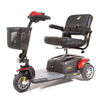
Visual identification of all major components of the Buzzaround Extreme scooter.
Lists and describes the function of key components in the scooter's control system.
Information on the circuit breaker, battery packs, and battery harnesses.
Details the controller's role and the main wiring harness connectivity.
Information on the motor/brake assembly, brake, and intermediate connectors.
Details on throttle, speed controls, and the key switch for scooter operation.
Information and warnings regarding the off-board battery charger.
Detailed wiring diagram illustrating component interconnections for the scooter.
Procedure to check voltage at battery packs, power harness, controller, and main harness.
Steps to verify battery voltage at the charger port and test charger functionality.
Explains beep codes for low batteries, high voltage, and current limit timeouts.
Procedure to diagnose brake faults by checking park brake position and resistance.
Diagnosing paddle faults related to the throttle control lever's neutral position.
Steps to test throttle pot resistance at controller and throttle connectors.
Procedure to test motor resistance and continuity of the front intermediate harness.
Information and steps for diagnosing internal controller faults.
Instructions for replacing the drivewheel and drivetrain assemblies.
Procedure for replacing the throttle potentiometer assembly.
Detailed steps for safely replacing the scooter's battery packs.
Guide to replacing the circuit breaker and the main controller unit.
Instructions for replacing the control panel and the main wiring harness.
Steps for replacing the motor/brake assembly and the front intermediate harness.
Procedure for replacing the rear intermediate connector.
Instructions for replacing the power harness and its associated connectors.
Step-by-step guide on operating a multimeter to measure voltage.
Step-by-step guide on operating a multimeter to measure resistance.
| Maximum Speed | 5 mph |
|---|---|
| Range Per Charge | 18 miles |
| Ground Clearance | 3" |
| Battery Weight | 38 lbs |
| Tire Type | Flat-Free |
| Seat Width | 18 inches |
| Seat Depth | 16 inches |
| Overall Width | 23 inches |
| Drive Wheels | Rear Wheel Drive |
| Colors Available | Red, Blue |