Do you have a question about the Goldline AquaTrol and is the answer not in the manual?
Refer to diagrams for proper location of control's plug-in.
Refer to diagrams for proper location. Ensure connector snaps for reliable connection.
Plumb after filter/heater. For pool/spa combo, plumb before return valve.
Plumb in same section as Turbo Cell. Must have 12" (30cm) straight pipe run before it.
Maintain chemical makeup, salt level, and stabilizer for pool enjoyment and to prevent corrosion.
Relates calcium and alkalinity to water balance. Use equation/chart to determine Si.
Use only 99% pure sodium chloride (NaCl). Avoid rock salt, anti-caking additives, or iodized salt.
Add salt to pool with pump running. Drain to lower concentration. Allow 24 hrs for dispersion.
Set pool filter pump run time using trippers. Arrow indicates current time. Manual control available.
Modes: AUTO (normal), SUPER CHLORINATE (shock), OFF (no chlorine generation).
Controls chlorine output. Raise to increase, lower to decrease. Adjust for pool conditions.
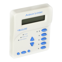
POWER, GENERATING, SUPER CHLORINATE LEDs indicate system status and conditions.
Sequential button pushes display pool temp, cell voltage/current, salinity, product name, software revision.
Addresses issues like no power, pump not running, no generation, flashing LEDs, and low/no chlorine.
Inspect cell every 3 months or after filter cleaning. Clean if scale appears. Use mild acid wash if needed.
Drain system before freezing. Balance water chemistry before starting in spring.
Balance pool chemistry before activation. Add metal remover and algaecide if needed for new water.
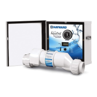
Mount control in raintight enclosure, min. 2m (5ft) from pool. Ensure ventilation for heat sink.
Install right-angle adaptor below return jet for gas dissipation. Mount cell vertically. Hand-tighten unions.
Use GFCI receptacle. Twist lock models use GFCI breaker. Ground and bond unit properly.
5-year warranty for Canada. Repair/replace defective product within 3 years, 60% charge after 3 years.
1-year warranty on parts/accessories. Repair/replace defective product within 1 year.
Excludes issues from improper installation, lack of maintenance, tampering, accidents, or acts of God.
The Aqua Trol Above-Ground Pool Automation is an advanced system designed for automatic chlorine generation in above-ground pools. It integrates a built-in filter pump timer, making it a comprehensive solution for pool sanitation and filtration management. The system operates by converting a low concentration of salt (sodium chloride) in the pool water into free chlorine through a process called electrolysis. This free chlorine effectively kills bacteria and algae, ensuring a clean and sanitized pool. A key advantage of this system is its continuous recycling of chlorine back into sodium chloride after sanitation, which significantly reduces the need for manually adding sanitizing chemicals. Salt replenishment is primarily required when water is lost due to backwashing, draining, or splashing, as salt is not lost through evaporation.
The core function of the Aqua Trol Above-Ground Pool Automation is to produce hypochlorous acid, which acts as the primary sanitizing agent. It is designed to effectively treat most residential above-ground pools. The actual amount of chlorination needed can vary based on factors such as bather load, rainfall, ambient temperature, and the overall cleanliness of the pool. The integrated timer ensures that the pool filter runs for the appropriate duration daily, facilitating both filtration and sanitization. The cell, where chlorine generation occurs, can be mounted directly to the pool return jet, and electrical connections are made via a standard 120V/15A "straight blade" line cord and receptacle.
To ensure optimal performance and longevity of the Aqua Trol system, maintaining proper water chemistry is crucial. The recommended water parameters include specific ranges for free available chlorine, pH, total alkalinity, calcium hardness, salt, and cyanuric acid (stabilizer). The system requires a salt level between 2700-3400 ppm, with 3200 ppm being ideal. Low salt levels can reduce the efficiency of chlorine production, while excessively high levels can cause the system to shut down and may impart a salty taste to the pool water. Stabilizer (cyanuric acid) is important for outdoor pools to protect chlorine residuals from degradation by sunlight. It is recommended to avoid adding pool chemicals directly to the skimmer, as this can damage the cell. Regular testing of pool water is advised, and local pool stores can assist with chemical adjustments.
The Aqua Trol system features a timer for controlling the pool filter pump. The timer is set by rotating clock hands to the current time, and small slide trippers on the outside of the timer control 15-minute intervals for desired pump run times. Trippers pushed IN (toward the center) indicate OFF, while trippers pulled OUT (away from the center) indicate ON. A manual control switch on the timer allows for manual pump operation.
The main switch has three positions:
A "Desired Level %" adjustment knob allows users to control the amount of chlorine generated. Increasing the setting raises chlorine levels, while lowering it decreases them.
Indicator LEDs provide status information:
The Salt Display shows the current salt concentration in ppm (parts per million). The display can be switched to Metric units (grams per liter) and temperature to Celsius by a specific sequence involving the "diagnostic" button and main switch.
Regular maintenance is essential for the Aqua Trol Above-Ground Pool Automation. It is recommended to visually inspect the cell every 3 months or after cleaning the filter. The system will prompt an "Inspect Cell" LED flash after approximately 500 hours of operation. After inspection and cleaning, pressing the "diagnostic" button for 3 seconds resets the timer for the next 500-hour inspection period.
The electrolytic cell incorporates a self-cleaning feature that typically maintains optimum efficiency. However, in areas with hard water or if water chemistry is unbalanced, periodic cleaning may be necessary. If the "Inspect Cell" LED remains on after thorough cleaning, the cell may be worn and require replacement. Only replacement cells specifically labeled for the Aqua Trol Above-Ground Pool Automation, with registration number 28593, should be used. The typical life expectancy of the electrolytic cell is 10,000 hours under normal use.
This method is reserved for severe cases where flushing and scraping are insufficient.
The electrolytic cell and flow detection switch are susceptible to damage from freezing water. In regions with severe or extended freezing temperatures, drain all water from the pump, filter, and supply/return lines. The electronic control unit is capable of withstanding winter weather and does not need to be removed.
Do not turn on the Aqua Trol Above-Ground Pool Automation until the pool water chemistry has been brought to the proper recommended levels.
| Type | Salt Chlorine Generator |
|---|---|
| Salinity | 2500-4500 ppm |
| Flow Rate | 20 GPM |
| Plumbing Size | 2 inch |
| Voltage | 120V or 240V |