Page 2
InstallationInstallation
InstallationInstallation
Installation
Setup
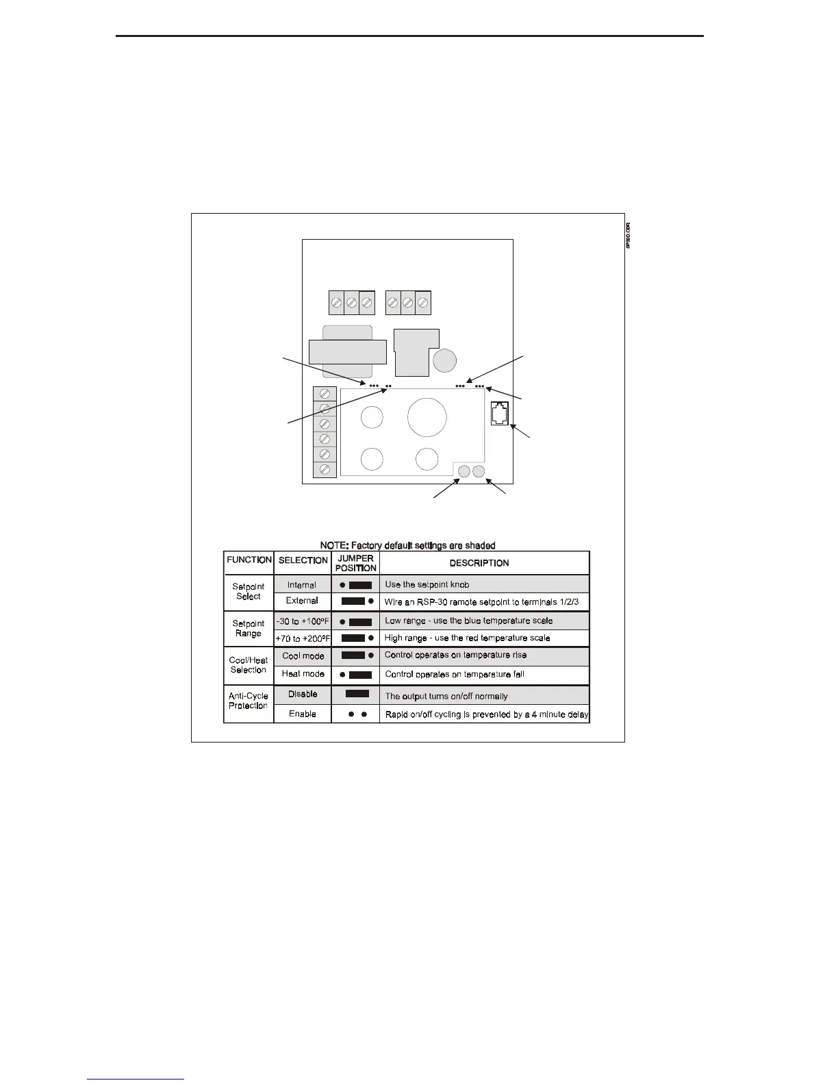
The SP-30 and SP-30D can be configured to
operate in a variety of applications using jumpers
located on the circuit board (see diagram below).
Set these jumpers based on your application,
before attempting to install or wire the control.
The jumper functions and appropriate positions
are shown in the diagram below.
SETPOINT
DIFF 1
R
C
1
2
3
4
Setpoint
Selection
Anti-Cycle
Protection
Cool/Heat
Selection
Setpoint
Range
Connector
for TD-30
Power LED
Output LED
 Loading...