Do you have a question about the Goldstar LWC061JGMK1 and is the answer not in the manual?
Before servicing the unit, read the safety precautions.
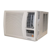
Lists the specific models covered by this service manual.
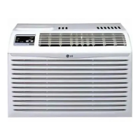
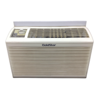
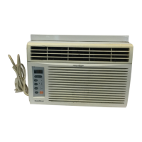
Highlights key design aspects and benefits of the room air conditioner.
Essential safety guidelines to follow before and during servicing.
Procedure for testing insulation resistance to prevent shock hazards.
Details the functions of various buttons on the air conditioner's control panel.
Instructions on how to properly insert batteries into the remote controller.
Section detailing the mechanical components for disassembly.
Step-by-step guide to removing and reinstalling the front grille.
Procedure for removing and reinstalling the main cabinet.
Steps for accessing and removing the control board.
Instructions for removing and reinstalling the upper air guide component.
Detailed steps for disassembling the orifice, turbo fan, and fan.
Procedures for removing and reinstalling the air guide.
Overview of electrical components for service.
Steps to remove and replace the overload protector.
Instructions for safely discharging and removing the capacitor.
Procedure for removing and replacing the thermistor.
Steps to remove the control panel assembly.
Section detailing the refrigerant cycle components and flow.
Steps to remove and reinstall the condenser unit.
Procedure for removing and reinstalling the evaporator unit.
Important notes regarding refrigerant cycle replacement and evacuation procedures.
Warning regarding high vacuum equipment use and oil foaming.
Diagram illustrating the vacuum pulling process for the refrigeration system.
Diagram showing the charging process for the refrigeration system.
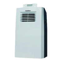
Guidance on choosing the optimal location for installing the air conditioner.
General instructions for installing the unit.
Specifications and requirements for window installation.
Lists and describes the hardware components required for installation.
Step-by-step guide for installing the air conditioner in the window.
Important safety warnings to be observed during installation.
Key information regarding centering the air conditioner in the window.
Instructions for securing the guide panels to fill the window opening.
Steps for installing the sash seal and sash lock.
Guidance on securing the drain pipe to prevent water overflow.
Information on power supply, cord plug, and extension cord usage.
Recommendations and cautions regarding the use of extension cords.
Diagrams and measurements for the external dimensions of the unit.
Explanation of the refrigeration cycle and component functions.
Troubleshooting steps for when the unit runs but provides ineffective cooling.
Diagnostic steps for when the compressor fails to start.
Troubleshooting guide for when the fan motor fails to start.
Troubleshooting steps for when the unit does not operate at all.
Steps to diagnose why the compressor is not operating.
Troubleshooting steps for when the compressor always operates.
Diagnostic guide for when the fan does not operate.
Troubleshooting steps for a non-operational remote controller.
Troubleshooting steps for abnormal display on the unit.
Detailed troubleshooting for a fan motor that fails to run.
Troubleshooting steps when the fan motor runs but may have issues.
Causes and remedies for fan motor noise issues.
Troubleshooting steps when the compressor fails but the fan runs.
Diagnosing and resolving compressor overload cycling issues.
Further troubleshooting for compressor overload conditions.
Steps to diagnose and fix insufficient cooling problems.
Causes and remedies for excessive noise generated by the unit.
Electrical circuit diagrams for various models of the air conditioner.
Table listing component locations, descriptions, and quantities.
Detailed schematic of the microcontroller unit and its connections.
Diagram showing the LED module and its component layout.
Layout diagram for components on the display Printed Wiring Board assembly.
Illustrated exploded view of the unit with part numbers indicated.
Comprehensive list of service parts with location, description, part numbers, and remarks.
Continued list of service parts, detailing part numbers for different models.
Publication information including date and printing location.
| Brand | Goldstar |
|---|---|
| Model | LWC061JGMK1 |
| Category | Air Conditioner |
| Language | English |