EasyManua.ls Logo

Gonset G-66 - Service and Alignment; Lubrication; Malfunctioning; Alignment Procedure

Default Icon
17 pages
Print Icon
To Next Page IconTo Next Page
To Previous Page IconTo Previous Page
Loading...
SERVICE
INSTRUCTIONS
LUBRICATION
All
mechanical
parts
of
the
receiver
have been
fac-
tory
lubricated
and
further
lubrication
is
not
recom-
mended
until
the
need
becomes
obvious.
‘The
band-
switch
and
tuning
mechanisms
can
become
stiff
or
erratic
in
operation
after
extended
use
and
this
may
be
remedied
by
the
sparing
application
of
Lubriplace
or
a
similar
lubricant.
Clean
the
pare
thoroughly
with
carbon
tetrachloride
before
applying
aew
tub
cation.
An
occasional
cleaning
of
the
entire
chassis
with
a
small
brush
or
dry
compressed
air
is
advisable.
Make
certain
that
no
components
of
the
set
are
dis-
turbed
during
this
operation.
MALFUNCTIONING
Experience
has
shown
that
nearly
90%
of
the
causes
of
malfunctioning
are
traceable
to
defective
tubes.
‘Therefore,
when
the
reason
for
lack
of
per-
formance
is
not
immediately
obvious,
check
all
tubes
before
proceeding
further.
All
component
parts
in
the
G-66
are
operated
well
below
maximum
ratings
and
parts
failures
will
be
very
infrequent,
ALIGNMENT
Realignment
of
the
receiver
should
be
considered
only
when
lack
of
sensitivity
or
selectivity
is
expe-
rienced
and
other
possible
causes
have
been
elimi-
nated.
Do
not
attempt
alignment
without
the
use
of
a
well-calibrated
signal
generator
of
good
quality,
If
possible,
the
signal
generator
should
be
checked
ainst
a
100-ke
crystal
frequency
standard
as
each
alignment
frequency
is
set
up.
Use
a
General
Cement
No.
GC-8606,
or
equivalent,
alignment
tool
for
rf-
coil_adjustments.
A
small
screwdriver,
preferably
insulated,
is
required
to
adjust
the
i-f
transformer
cores.
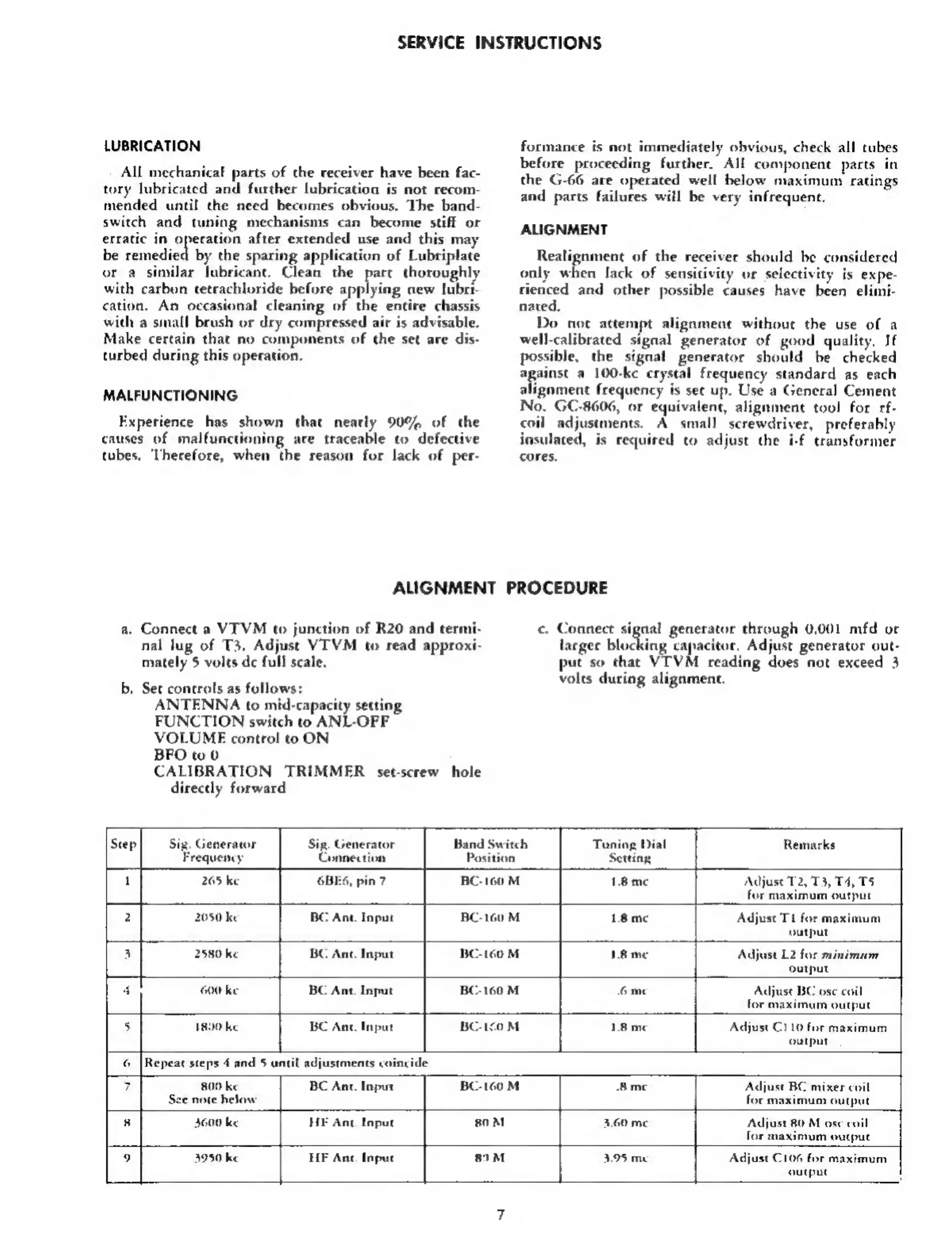
ALIGNMENT
PROCEDURE
a.
Connect
a
VTVM
to
junction
of
R20
and
cermi-
nal
lug
of
T3.
Adjust
VTVM
to
read
appro
mately
5
volts
de
full
scale.
b,
Sec
controls
as
follows:
ANTENNA
to
mid-capacity
setting
FUNCTION
switch
to
ANL-OFF
VOLUME
control
to
ON
BFO
tw
0
CALIBRATION
TRIMMER
set-screw
hole
directly
forward
c.
Connect
signal
generator
through
0.001
mfd
or
larger
blocking
capacitor,
Adjust
generator
out-
put
so
that
VTVM
reading
does
not
exceed
3
volts
during
alignment.
Step]
Sig,
Generator
Sig.
Generator
Band
Switch
Tuning
Dial
Remarks
Frequency
Connection
Po
s
1
265
ke
6BES,
pin
7
BC-160
M
Adjust
12,
T3,
14,
T5
for
maximum
output
2
2050
ke
BC
Ant.
Input
BC-160
M
1.8m¢
Adjust
T1
for
maximum
output
3
2580
ke
BC
Ant.
Input
OM
IR
me
Adjust
L2
for
minimum
output
4
600
ke
BC
Ant.
Input
60
M
6me
Adjust
BC
ose
coil
for
maximum
output
5
1890
ke
BC
Ant.
Input
BC-1c0
M
1.8
me
Adjust
C110
for
maximum
output
6
[Repeat
steps
4
and
5
until
adjustments
coincide
7
809
ke
BC
Ant.
Input
BC-160
M
-Bmc
Adjust
BC
mixer
coil
See
note
helow
for
maximum
output
8
3600
ke
HF
An.
Input
80M
3.60
me
Adjust
80
M
ose
coil
for
maximum
output
9
3950
ke
HE
Ane.
Inpuc
89M
3.95
me
Adjust
C106
for
maximum
output