EasyManua.ls Logo

Gooligum Electronics Baseline and Mid-Range PIC - User Manual

Gooligum Electronics Baseline and Mid-Range PIC
31 pages
Print Icon
To Next Page IconTo Next Page
Loading...
© Gooligum Electronics 2015 www.gooligum.com.au
Baseline and mid-range PIC training and dev board operation guide Page 1
Baseline and Mid-Range PIC (6 14 pin)
Training and Development Board
Construction and Operation Guide
This PIC development board is designed as a training environment specifically for use with the
introductory Gooligum baseline, mid-range and enhanced mid-range PIC tutorials
1
.
The tutorials were originally written for Microchip’s Low Pin Count Demo Board, which supports 8-, 14-
and 20-pin PICs, can be used easily with a PICkit 2 or PICkit 3 programmer, and provides four LEDs, a
pushbutton switch and a potentiometer. As such, it’s a good, simple introductory board. However, it does
not support the 6-pin 10F PICs and its LEDs cannot be used directly with 8-pin PICs.
More significantly, many of the Gooligum baseline and mid-range lessons require the use of parts not
included on that board, such as photocells, crystal-driven oscillator circuits, and 7-segment LED displays.
Although it is possible to build all of these circuits on a breadboard, connected to the Low Pin Count
Demo Board, it is a little cumbersome especially for some of the more complex circuits.
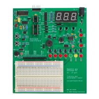
This training board was developed to make it easy to follow the Gooligum baseline, mid-range and
introductory enhanced mid-range lessons. It works with a PICkit 2 or PICkit 3 programmer, and supports
all 8- and 14-pin baseline, mid-range and enhanced mid-range PICs, as well as all 6-pin 10F devices (in an
8-pin DIP package). It is fully configurable using the provided jumpers, and comes with all of the
hardware needed for every introductory lesson, including all the required PICs.
It features:
Support for all 6-pin, 8-pin and 14-pin baseline, mid-range and enhanced mid-range PICs
(all 10F, 12F and 14-pin 16F devices)
2 × pushbuttons (including MCLR )
o optional external pull-up resistor on each pushbutton
9 × LEDs
o an LED is available on each 6-pin and 8-pin PIC output pin, plus pins RC0 RC3
3 × 7-segment LED displays
o configurable as a single digit or multiplexed digits
External 32.768 kHz oscillator
o can be configured to drive processor clock, Timer0 or Timer1
4 MHz resonator, 32.768 kHz crystal and resistor/capacitor for use with processor oscillator
o 32.768 kHz crystal also available for Timer1 oscillator
Potentiometer and 2 × photocells for use as analog inputs in comparator and ADC lessons
Variable frequency oscillator for frequency and pulse width measurement lessons
Piezo sounder, to demonstrate PWM outputs
Standard ICSP connector for use with PICkit 2 or PICkit 3 programmer
1
All baseline, mid-range, and introductory enhanced mid-range assembler and C lessons
Question and Answer IconNeed help?

Do you have a question about the Gooligum Electronics Baseline and Mid-Range PIC and is the answer not in the manual?

Overview

The Gooligum Baseline and Mid-Range PIC Training and Development Board is a versatile platform designed for learning and experimenting with Microchip's Low Pin Count (LPC) PIC microcontrollers. It supports a range of PICs, including 8-, 14-, and 20-pin devices, and is compatible with PICkit 2 and PICkit 3 programmers. The board's design emphasizes ease of use, with a breadboard area for custom circuits and clearly labeled components.

Function Description

The training board provides a comprehensive set of peripherals and interfaces for developing and testing PIC microcontroller applications. Key functions include:

  • PIC Microcontroller Sockets: The board features multiple DIP IC sockets to accommodate various 8-pin, 14-pin, and 20-pin PIC microcontrollers. This allows users to experiment with different PIC families and their respective features.
  • Power Supply: The board can be powered by a PICkit 2 or PICkit 3 programmer (supplying up to 30 mA) or an external regulated 5V power supply (via a 5.5 mm barrel DC plug). A diode provides polarity protection, and the board is designed for PICs operating up to 5.5V.
  • Digital I/O:
    • LEDs: Nine 5mm LEDs (red, green, or yellow) are connected to various PIC output pins via jumpers and 330 Ω resistors. This allows for visual feedback and debugging of digital output.
    • Pushbutton Switches: Two 6mm PCB-mount tactile pushbutton switches are connected to PIC input pins (GP/RA/RB2 and GP/RA/RB3/MCLR) via 1 kΩ isolation resistors. These are active low inputs, and external 10 kΩ pull-up resistors can be enabled via jumpers.
    • 7-Segment LED Displays: Three common-cathode 7-segment LED displays are included. Segments A-D, F, and G are connected via 330 Ω resistors and jumper block JP4 to PIC pins RA/RB0-1 and RC1-4. Segment E can be connected to RA/RB2 or RA/RB4 via JP5. The common cathodes of the digits are controlled by NPN transistors, allowing for multiplexing. Jumpers JP6, JP8, JP9, and JP10 configure the display for single, two-digit, or three-digit operation.
  • Analog I/O:
    • Potentiometers and LDRs: A 10 kΩ potentiometer and two light-dependent resistors (LDRs or CDS photocells) are available as analog voltage sources. They can be connected to ADC or comparator inputs (ANO/CIN+/C1IN+ via JP24, and AN2/C2IN+/C1IN- via JP25).
  • Oscillator Section:
    • 32.768 kHz Oscillator: An onboard 32.768 kHz watch crystal oscillator (implemented with a watch crystal and CMOS inverter) provides a buffered output that can drive Timer0 (in counter mode via JP22) or serve as an external signal for the processor clock (via JP20).
    • 4.00 MHz Ceramic Resonator: A 4.00 MHz ceramic resonator with a built-in capacitor is provided for use with the PIC's internal oscillator (connected via JP20 and JP21).
    • RC Oscillator: A 10 kΩ resistor and 82 nF capacitor can be connected via JP20 to OSC1 to form an external RC oscillator with a frequency of approximately 1 kHz.
  • Piezo Sounder: A 13mm PCB external drive piezo sounder is included, connected to RC5 (PWM output) and P1A (other side to ground via JP23).
  • Variable Frequency Oscillator (VFO): A 555 timer-based VFO generates a signal with a frequency variable from approximately 150 Hz to 10 kHz using trimpot RP1. This digital signal can be connected to the Timer 1 gate input (T1G) or the capture input pin (CCP1) via jumper block JP26.
  • Expansion Header: A 16-pin expansion header allows for connecting custom circuits built on the provided breadboard, extending the board's functionality.

Important Technical Specifications

  • Supported PICs: 8-pin, 14-pin, and 20-pin baseline and mid-range PICs (e.g., PIC10F200, PIC12F509, PIC16F684).
  • Power Input:
    • PICkit 2/3: Up to 30 mA.
    • External DC Power Jack: 5.5 mm barrel, 2.1 mm positive center pin, regulated 5V (recommended, provides ~4.3V to PIC after diode drop), max 6V.
  • LEDs: 9 x 5mm LEDs (red, green, yellow), connected via 330 Ω resistors.
  • Pushbutton Switches: 2 x tactile switches, active low, with 1 kΩ isolation resistors and optional 10 kΩ pull-up resistors.
  • 7-Segment Displays: 3 x common-cathode 7-segment LED displays.
  • Analog Inputs: 10 kΩ potentiometer, 2 x CDS photocells (LDRs, 20-60 kΩ when illuminated).
  • Oscillators:
    • 32.768 kHz watch crystal.
    • 4.00 MHz ceramic resonator.
    • RC oscillator (10 kΩ resistor, 82 nF capacitor).
    • 555 timer-based variable frequency oscillator (150 Hz – 10 kHz).
  • Piezo Sounder: 13mm PCB external drive piezo sounder.
  • Connectors: ICSP header, DC power jack, 16-pin header socket, 6-pin right-angle header, various snappable headers (32-pin, 9-pin, 2x19-pin).
  • Resistors: Various 1/4W resistors (330 Ω, 1 kΩ, 4.7 kΩ, 10 kΩ, 22 kΩ, 100 kΩ, 10 MΩ).
  • Capacitors: Various ceramic capacitors (22 pF, 3.3 nF, 10 nF, 47 nF, 82 nF, 100 nF, 1 µF).
  • Transistors: 3 x BC337 NPN transistors (or similar).
  • Diodes: 1 x 1N400x series rectifier diode, 2 x 1N4148 diodes (additional components).
  • IC's: NE555 timer, 74HCU04N hex inverter (unbuffered), 74HC14N hex Schmitt-trigger inverter (additional component).

Usage Features

  • Jumper-Configurable: The board is highly configurable using a system of header shunts (jumpers). This allows users to easily connect and disconnect different components to PIC pins without soldering, facilitating rapid prototyping and experimentation. A detailed jumper summary is provided in the manual.
  • Breadboard Area: A dedicated 2" x 3" solderless breadboard area is integrated into the PCB, allowing users to build custom circuits and interface them with the PIC microcontroller via the expansion header.
  • Clear Labeling: All components, jumpers, and PIC pins are clearly labeled on the PCB overlay, making it easy to identify connections and configure the board.
  • Tutorial-Driven Learning: The board is designed to be used with Gooligum tutorials, which guide users through various lessons using baseline, mid-range, and enhanced mid-range PICs. The tutorials provide specific jumper configurations for each example.
  • Multiple PIC Support: The inclusion of various DIP IC sockets and additional PIC microcontrollers (e.g., PIC10F200, PIC12F509, PIC16F684) allows users to explore different PIC architectures and their unique features.
  • External Power Option: The ability to use an external regulated 5V power supply is useful for applications requiring more current than the PICkit programmer can provide, or when operating the board standalone.

Maintenance Features

  • Robust Design: The PCB-mounted components and clear layout contribute to a robust design suitable for repeated use in a learning environment.
  • Replaceable Components: Most components are standard through-hole parts, making them relatively easy to replace if damaged.
  • Jumper System: The jumper system simplifies troubleshooting by allowing individual components or sections of the circuit to be isolated or reconfigured.
  • Parts List: A comprehensive parts list is provided in the manual, detailing all PCB-mounted components and additional components supplied for tutorials. This aids in identifying and sourcing replacement parts.
  • Schematics: Detailed schematics are included in the manual, providing a clear understanding of the board's internal circuitry, which is invaluable for advanced troubleshooting or customization.
  • No Voltage Regulator: The absence of an onboard voltage regulator means users must supply a regulated power source. While this requires careful attention to the input voltage, it also simplifies the board's design and reduces potential points of failure associated with regulators.

Gooligum Electronics Baseline and Mid-Range PIC Specifications

General IconGeneral
BrandGooligum Electronics
ModelBaseline and Mid-Range PIC
CategoryMotherboard
LanguageEnglish