© Gooligum Electronics 2015 www.gooligum.com.au
Baseline and mid-range PIC training and dev board operation guide Page 2
Every PIC pin is brought out to the header at the bottom of the board, allowing the easy prototyping on the
breadboard of circuits not covered by the onboard components, including circuits which require more than
the 20 mA or so that a PICkit 2 or PICkit 3 can deliver, through the use of an external regulated DC power
supply.
So, when you’ve completed all the lessons, you can continue to use the board for PIC development.
Construction
[If your training board came fully assembled, you can ignore this section…]
The training board kit consists of a printed circuit board, a set of components to be soldered to the board,
jumper shunts, rubber feet, a solderless breadboard, and solid hook-up wire (for use with the breadboard).
It also comes with a bag of additional components for use with some of the Gooligum tutorial lessons –
these are not to be mounted on the PCB. See the parts list, in appendix B, for details.
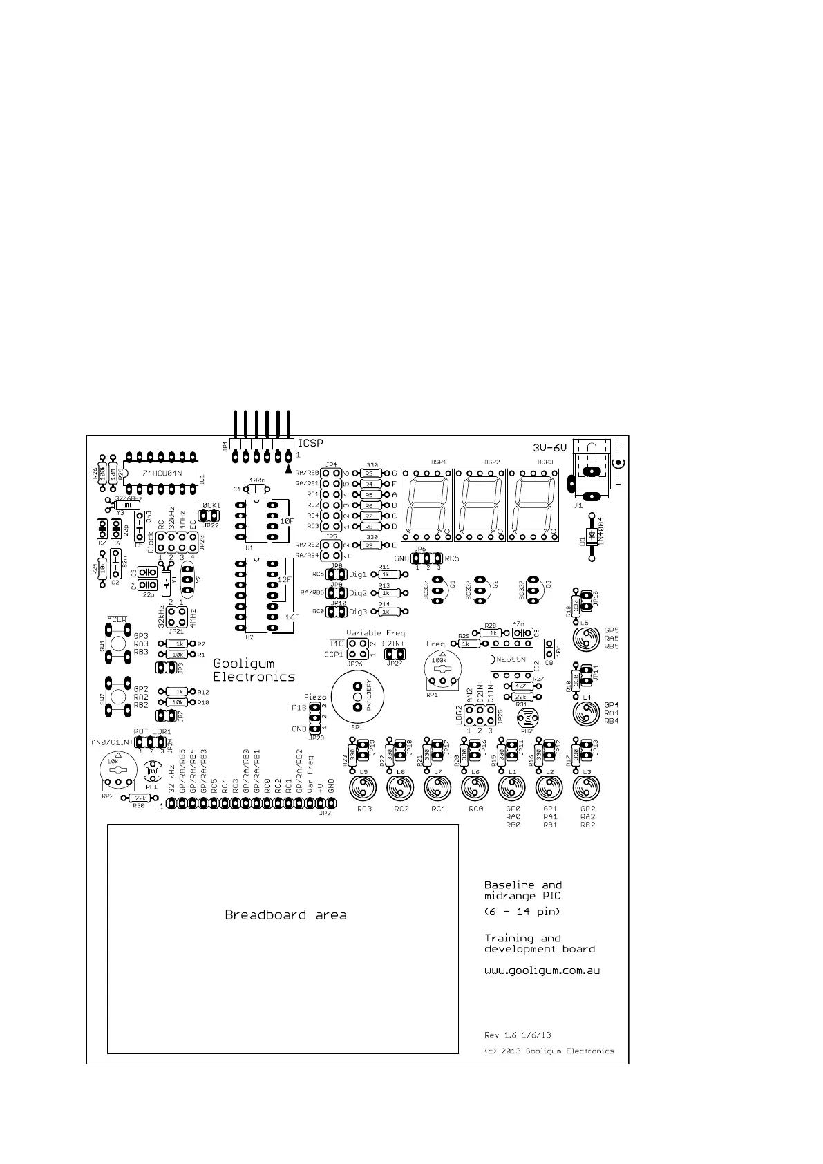
Construction is straight-forward, only needing basic soldering skills. All components are through-hole,
and a component overlay (as shown below) is provided on the PCB.
 Loading...