Do you have a question about the Gopel Electronic G PCIe and is the answer not in the manual?
Provides guidance on document usage, safety, and symbol explanations.
Details the specific applications and purpose of the Multibus Controller 6281.
Outlines electromagnetic compatibility requirements and protection measures.
References the EU Declaration of Conformity for the product.
Lists general safety instructions to prevent injury and property damage.
Defines limitations on liability and warranty for product use.
Lists the accessories included with the Multibus Controller 6281.
Specifies the hardware and software prerequisites for the system.
Instructions for installing the G PCIe and G PXIe plug-in cards.
Instructions for installing the G CAR 6281 stand-alone box.
Information on installing Windows device drivers for the controller.
Guidance on installing the GÖPEL electronic Application Programming Interface.
Steps to configure network settings for communication.
Configuring IP addresses and subnet masks for network communication.
Using Hardware Explorer to view and change device IP addresses.
Guidance on configuring static IP addresses for multiple devices.
Detailed steps for removing and installing transceiver modules.
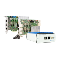
Overview of the Multibus Controller 6281 as an automotive test system.
Details on PCIe and PXIe plug-in card specifications and features.
Identification of components on the G PCIe 6281 board.
Identification of components on the G PXIe 6281 board.
Overview of connectors and indicators on the G CAR 6281 DUT side.
Overview of connectors and indicators on the G CAR 6281 rear side.
Details on processor, RAM, flash, dimensions, and weight.
Provides supply voltage and power consumption details.
Schematic representation of the Multibus Controller 6281's internal architecture.
Details the pinout for the four RJ.5 connectors.
Pin configuration for the D-SUB9 adapter cable.
Lists article numbers for TE Connectivity RJ.5 to RJ.5/RJ.5 to RJ45 cables.
Description of the RJ45 Ethernet socket for control and data.
Explanation of the status LEDs on the front panel.
Details of the external 12 VDC power adapter.
Pinout of the power supply connector.
Explanation of galvanic isolation for protection and error prevention.
Description of SYNC connectors for multi-device synchronization.
Table showing transceiver assignment to external voltage inputs.
Table detailing interface assignments for different firmware variants.
Electrical characteristics and G-API commands for CAN/CAN FD.
Electrical characteristics and G-API commands for LIN/K-Line.
Electrical characteristics for the K-Line transceiver.
Specifications and G-API commands for FlexRay interfaces.
Details on Automotive Ethernet interfaces and transceiver.
Overview of the TAP matrix for connecting Ethernet interface resources.
Electrical characteristics for digital inputs and outputs.
Pinout for the additional Digital I/O connector on G PXIe 6281.
Description of SENT inputs/outputs and licensing.
Using the C-based user interface for hardware control.
Using LabVIEW VIs for controller access.
Executing user programs directly on the internal processor.
Accessing and managing files on the onboard file system.
Recording and playback of firmware commands as sequences.
Creating and executing residual bus simulations.
Executing self-created onboard programs and communication via FIFOs.
Procedures for resetting device configurations via G-API or HardwareExplorer.
Lists additional options and accessories for the controller.
Details the warranty period and conditions for repair.
Guidance on identifying the system for warranty or repair services.
EU directives for WEEE and RoHS compliance for disposal.
Instructions for disposing of disposable and rechargeable batteries.
Specifies the product name and relevant standards.
Information on product marking (e.g., CE mark).
| Brand | Gopel Electronic |
|---|---|
| Model | G PCIe |
| Category | Controller |
| Language | English |