EasyManua.ls Logo

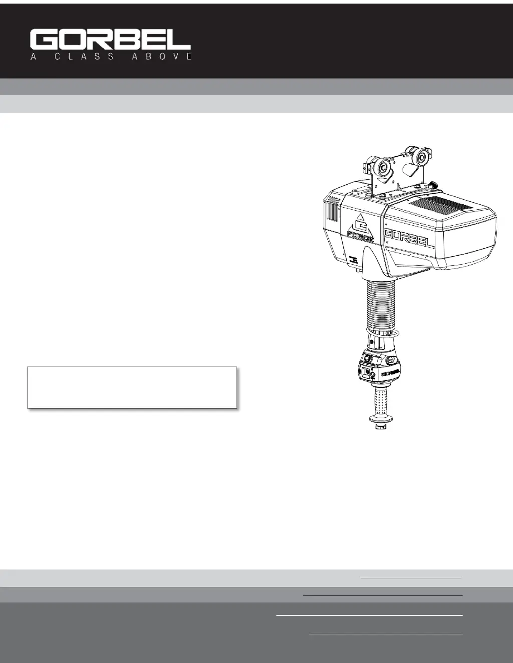
GORBEL G-Force Q2 Series - User Manual

GORBEL G-Force Q2 Series
92 pages
Print Icon
To Next Page IconTo Next Page
Loading...
G-Force
®
Q2 and iQ2 Series
®
Date
Month Year
Gorbel
®
Dealer
Rev C released: 12/2020
Gorbel
®
Customer Order No. / Serial No.
Original manual released: 06/2020
IMPORTANT!
DO NOT DESTROY
OR DISCARD.
Default Settings for your G-Force
®
unit:
AP SSID: G-Force AP Order Number
AP Password: Order Number
Installation,
Operation, &
Maintenance
Manual

Table of Contents

Other manuals for GORBEL G-Force Q2 Series

Questions and Answers

  • T
    Taylor LawsonAug 18, 2025
    What to do if the GORBEL Controller unit will not raise or lower the load?
    • S
      Sandra Rose DDSAug 18, 2025
      If the GORBEL Controller unit isn't raising or lowering the load: * Ensure you are in RUN MODE. * Check virtual limits settings if equipped. * Verify you are not in an overloaded condition. * If wearing dark gloves, remove them and try the sliding handle again. * Check the coil cord for secure connections at both the handle and the actuator. * Ensure the sliding handle grip or pendant handle levers move smoothly. * Check for any interference between the handle and any foreign objects, work surfaces, etc.
  • B
    Bailey AndersonAug 21, 2025
    What does it mean when my GORBEL Controller displays E501 / E11000 codes?
    • J
      jodi34Aug 21, 2025
      E501 / E11000 codes on your GORBEL Controller indicate a limit switch fault. Here’s what to check: * Look for any mechanical binding that could engage both the upper and lower limit switches. * Check and correct if the limit switch cable is connected to the interface board. * Check for bad electrical connection or shorted wires from the switches.
  • B
    Brett MorrisonAug 23, 2025
    What does it mean when my GORBEL Controller displays E7219 / E4005 codes?
    • P
      Pamela RoachAug 23, 2025
      E7219 / E4005 codes on your GORBEL Controller mean the AC power is too low. If it approaches approximately 200VAC, the system won't operate properly.
  • J
    Jake BuckAug 26, 2025
    What to do if there is a fault or warning message displayed on the OLED screen on the GORBEL Controller handle?
    • P
      Patricia CurtisAug 26, 2025
      If a fault or warning message appears on the OLED screen of your GORBEL Controller handle: * Clear the fault condition per the instructions on the OLED. * Reset the E-stop on the handle. * Cycle the AC power. Note: AC power must be disconnected from the actuator by unplugging the actuator from the AC power source or disconnecting power by using a circuit breaker or similar method.
  • O
    osullivanAug 28, 2025
    Why GORBEL Controller unit only goes in the up direction?
    • D
      daniel84Aug 28, 2025
      If your GORBEL Controller unit only moves upwards, check the following: * Verify the virtual limits settings if that option is active. * Ensure the wire rope is not slack. * Check that no inhibit down motion inputs have been enabled. * Look for any obvious interference with the load or the handle. * Make sure you are not at the system's lower limit. * Check the coil cord connections at both the handle and actuator. * Inspect the overall condition of the coil cord for broken or exposed wiring.
  • A
    Alison SpearsAug 30, 2025
    Why GORBEL Controller unit only goes in the down direction?
    • C
      Carmen ColonAug 30, 2025
      If the GORBEL Controller unit only goes in the down direction, consider these possible causes: * Check the virtual limits settings if that option is active. * Ensure you are not at the upper limit of the system. * Verify that no inhibit up motion inputs have been enabled. * Check that you are not in an overload condition. * Check for any obvious interference with the load or the handle. * Check the coil cord connections at both the handle and actuator. * Check the overall condition of the coil cord. Look for broken or exposed wiring.
  • S
    Sara WoodsSep 2, 2025
    How to fix Float Mode if it does not function correctly on GORBEL Controller?
    • D
      Daniel ChapmanSep 2, 2025
      To troubleshoot Float Mode issues on your GORBEL Controller: * Check that the blue LED on the handle is illuminated. * Verify the OLED screen indicates you are in Float Mode. * Ensure Float Mode hasn't timed out due to inactivity (default is 60 seconds). * Make sure the unit is stable when Float Mode is initiated. * Check that the load data is reading accurately on the OLED screen. * Verify the bridge capacity. * Check for excessive deflection in the bridge. * Check for obvious interference with the coil cord or handle.
  • T
    Tiffany ChoiSep 4, 2025
    What to do if there is no display on the OLED screen on the GORBEL Controller handle?
    • F
      Frank JohnsonSep 4, 2025
      If the OLED screen on your GORBEL Controller handle is blank: * Verify the correct AC power to the actuator. * Check the coil cord connections at both the handle and actuator. * Inspect the overall condition of the coil cord for broken or exposed wiring. * Ensure all connections to the Actuator PCB are securely connected.
  • J
    Joseph WilsonSep 7, 2025
    Why GORBEL Controller unit does not accelerate at the desired rate?
    • K
      Katie CunninghamSep 7, 2025
      If your GORBEL Controller unit isn't accelerating as expected: * Adjust the response in PROGRAM MODE. * Avoid attempting to “snatch” the load. * Check the load weight; if near the overload limit, try lifting at a reduced speed.
  • J
    James PettySep 9, 2025
    Why is the GORBEL Controller unit too slow or too fast?
    • C
      carolynperezSep 10, 2025
      If your GORBEL Controller unit operates at an undesired speed: * Adjust the speed in PROGRAM MODE. * Check for speed reduction setting in virtual limits program if that option is selected.

Summary

Safety and General Information

Safe Hoist Operating Guidelines

Provides essential safety rules for operating hoists and trolleys to prevent injury and damage.

G-Force Operational Guidelines

Key operational principles and safety precautions for using the G-Force unit.

Important Safety Instructions

Critical safety warnings and guidelines for installation and operation.

Introduction

Overview of the G-Force Intelligent Lifting Device and its benefits.

Installation Procedures

Correct G-Force Installation Orientation

Illustrates the proper mounting orientations for various G-Force handle types.

G-Force Main Assembly Component Description

Details the three main assemblies of the G-Force: Actuator, Coil Cord, and Handle.

Installation Steps

Comprehensive guide covering unpacking, pre-assembly, and core installation steps.

Handle Installation Procedures

Detailed instructions for installing various types of G-Force handles.

Final Installation and Setup

Covers electrical connection, initial power-up, float mode, and I/O block setup.

Lift Functionality and Controls

Standard Handle Operation Modes

Explains operation for slide, pendant, and force sensing handles.

Emergency Stop and Float Mode

Details the function of the E-stop button and Float Mode operation.

Program Mode and Diagnostic Features

Describes Program Mode access and diagnostic capabilities.

Faults, Overload, and Limit Switches

Explains system faults, overload conditions, and limit switch functions.

Slack Switch and Remote Handle Options

Details slack switch functionality and remote handle setup.

Controls Interface Features

Describes jog buttons, service mode, and communication ports.

Program Mode and HMI Visualization

Overview and Basic Operation

Introduction to Program Mode, navigation, and basic usage.

Handle Operation and Mode Features

Details on handle interaction, lockout features, and safety modes.

Program Mode Menus and Settings

Covers menus for Virtual Limits, Speed, Response, and Settings.

Advanced Program Mode Features

Details on Float Mode, I/O, Overload, and other advanced settings.

HMI Visualization Interface

Guide to connecting and navigating the HMI via VNC.

System and I;O Configuration Pages

Instructions for configuring system settings and I/O ports.

Program Menu Pages Overview

Overview of the various Program Menu pages and their functions.

Troubleshooting and Fault Log Access

Details on accessing diagnostics and the fault log via HMI.

Troubleshooting and Maintenance

Common OLED Display and Unit Issues

Troubleshooting steps for display, LED, and basic unit operation problems.

Operational and Error Code Issues

Resolving issues related to speed, acceleration, and specific error codes.

LED Status Chart

Chart detailing LED status indicators and corresponding machine states.

Technical Specifications

Key technical specifications for G-Force Q2 & iQ2 Actuators.

Wire Rope Inspection and Maintenance

Guidelines for inspecting and maintaining the hoist wire rope.

Wire Rope Replacement

Criteria and procedures for replacing the wire rope.

Slack Spring Adjustment

Procedure for adjusting the slack spring for optimal operation.

Recommended Tools & Spare Parts Kits

List of recommended tools and spare parts for maintenance.

Advanced Setup, Appendices, and Compliance

Dual Handle Setup Instructions

Steps for configuring and operating the G-Force with dual handles.

Appendix A - AP Field Customizations Instructions

Guide for customizing Access Point settings via wired connection.

Appendix B - AP VNC Viewer Install Instructions

Instructions for installing VNC viewer software for HMI access.

Appendix C - AP Connection QuickStart Guide

Quick guide for connecting to the G-Force AP wirelessly or via wire.

Appendix F - PC IP Address Setup for Wired Connections

Steps to configure PC network settings for wired connections.

Limited Warranty

Details the terms and conditions of the Gorbel Incorporated limited warranty.

CE Declaration of Conformity

Statement of compliance with relevant EU directives and standards.

Inspection and Maintenance Schedule

Schedule for routine inspection and maintenance of G-Force components.

GORBEL G-Force Q2 Series Specifications

General IconGeneral
Safety FeaturesEmergency stop, overload protection, anti-runaway protection, and various safety interlocks
Power SourceElectric
Operating ModesFloat Mode
CommunicationEthernet/IP, Modbus TCP
Control TypePendant or Remote
SpeedVariable
ConstructionSteel