INSTRUCCIONES DE ENSAMBLAJE
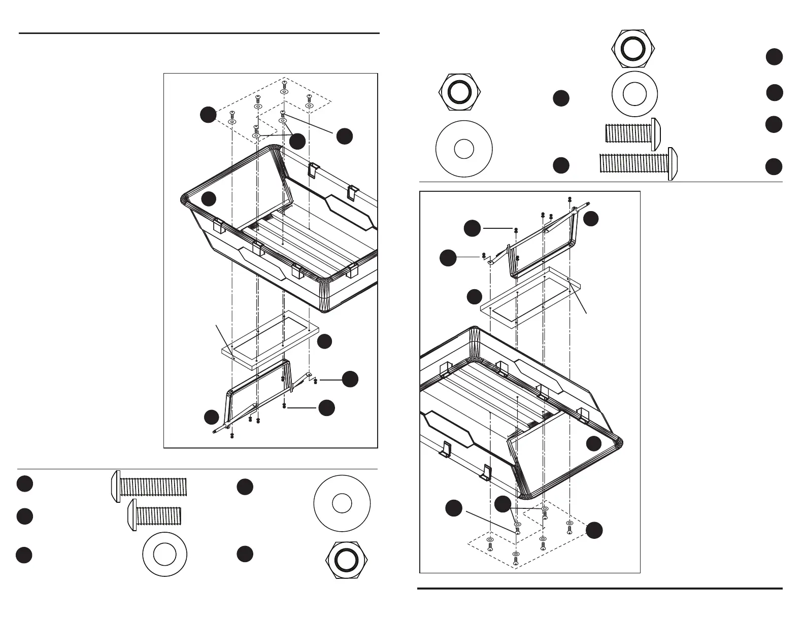
5. Fije el ensamble del eje
posterior (E) con los puntales
posteriores (C) y la estructura
posterior (D) a la bandeja (A)
con cinco pernos cabeza de
botón interna M8 x 30 mm
(BB), un perno de cabeza
segmentada M8 x 20 mm
(CC), seis contratuercas M8
(JJ), seis arandelas M8 (GG),
y seis arandelas M8 (FF),
como se muestra en la Fig. 7.
Use el pernos cabeza de
botón interna
M8 x 20 mm (CC) en la parte
central delantera de la
estructura posterior (D), como
se muestra en la Fig. 7.
6
Fig. 7
Aditamentos utilizados
El orificio más
cercano a la parte
posterior de la
bandeja
Consulte las
paso 4, fig. 5
para confirmar
que la colocación
esta correcto
El frente
de la
bandeja
M8 x 20mm
Perno cabeza de
botón interna
x 5
x 1
x 6
x 6
M8 x 30mm
Perno cabeza de
botón interna
Arandela plana M8
JJ
CC
Contratuerca M8
BB
FF
A
D
E
CC
GG
BB
JJ
FF
ASSEMBLY INSTRUCTIONS
Fig. 7
Hardware Used
5. Attach the rear axle
assembly (E) with the rear
struts (C) and the rear frame
(D) to the tray (A) using five
M8x25 internal button head
bolts (BB), one M8 x 20mm
internal button head bolt
(CC), six M8 lock nuts (JJ),
six M8 washers (GG), and six
M8 washers (FF), as shown
in Fig. 7.
Use the one M8 x 20mm
internal button head bolt (CC)
in the front center location of
the rear frame (D), as shown
in Fig. 7.
6
x 5
x 1
x 6
x 6
M8 Flat
Washer
JJ
CC
M8 Lock Nut
x 6
GG
M8 Flat
Washer
BB
FF
M8 x 20mm
Internal Button
Head Bolt
M8 x 25mm
Internal Button
Head Bolt
Hole
Closer
to rear
of tray
Note correct
position of rear
frame as noted
in Step 4,
Figure 5.
Front
of tray
A
D
E
JJ
CC
GG
BB
FF
x 6
JJ
Contratuerca
M8
x 6
GG
Arandela
plana M8
 Loading...