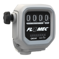
Oval gear flow meters have two clearly distinct portions: one of which is mechanical, wetted areas with the
oval gears surrounded by a housing, and the other is the electrical area, which includes the pulse output
board.
Details of some key troubleshooting steps will now be provided. Please also refer to the instructions on
troubleshooting errors contained on the following page.
Step 1 - Check application, installation and set-up. Carefully read the section on mechanical installation to
ensure full knowledge of all relevant installation and application factors which may affect the operation of
the counter. These include pulsation, trapped air or selecting the wrong counter, including incorrect flow
rate, temperature or pressure, or material incompatibility. Refer to the section on electrical installation to
ensure correct cabling.
Step 2 - Check for blockages. For new and modified systems in particular, the most frequent cause of error
or sub-optimal counter operation is internal system or counter blockages due to foreign particles, such as
beads of condensate, sealing tape residues or mixtures of deposits, rust, etc.
Step 3 - Guarantee flow rate. Flow stopping or a flow rate declining below the usual limit may be attribut-
able to a blocked screen, flow meter rotors which are stuck or damaged, a defective pump, closed valves or
an insufficient liquid level in the storage tank.
Step 4 - The oval gears in the counter must revolve. This rotation is audible: try holding a screwdriver blade
against the counter housing and push the handle right against your earlobe. Test the counter as required
with flow switched on and off, to ensure you are familiar with the audible sound of rotation.
Step 5 - Ensure that pulses are generated when liquids flow. Here, a multimeter is often not fast enough to
capture the pulse sequence of the reed switch or the Hall Effect sensor. However, an oscilloscope will allow
you to observe the output pulse sequence. When testing the reed switch pulse, a pull-up resistor must be
installed between the single connection of the reed switch and the supply voltage, while the other connec-
tion must be connected to the reference potential of the measurement device (oscilloscope)
Step 6 - Confirm device operation. Check the functions by simulating a pulse input. A reed switch pulse
input can be simulated by a swift and pulse-driven short-circuiting of the input terminals
Troubleshooting
Owner’s Operation Manual
Caution when operate.
DO NOT modify or alter the meter.
DO NOT leave the meter unattended while dispensing.
Check the meter daily. Worn or damaged parts should be repaired or replaced immediately.
DO NOT exceed the maximum working pressure level of the lowest rates system component.
Use only extensions and nozzles that are compatible with this meter.
Use only fluids and solvents that are compatible with the equipment. Notice the warnings for fluids and
solvents.
Tighten all fluid connections before operating the meter.
Comply with all local, state, and federal fire, electrical and safety regulations.
Use of the product in a manner other than specified in this manual may result in bodily injury or im-
paired operation or damage to the meter.
 Loading...