12
EN
REPAIR
(
CONTINUED
)
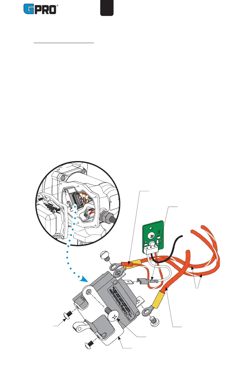
Replace Power Switch
1. Turn the pump OFF and disconnect from power.
2 Using a 4mm Hex wrench remove the (2) BHCS and nozzle cover.
4. Remove the (6) M6 SHCS and electrical cover plate from the motor
housing.
5. Remove the (1) #10 truss head screw and switch bracket with switch
assembly (see Figure 4).
6. Unscrew both #6 machine screws and remove the switch assembly from the
switch bracket.
7. Unscrew/unplug three blade terminals and remove red and white wires from
the switch (see Figure 4). Take note of which wire is attached to each blade
terminal for reinstallation.
8. Install a new switch by reversing the above procedure. Insert the switch
assembly into the pump cavity. Reinstall all components and tighten bolts
securely.
Figure 4
#6 Machine
screws
#10 Truss
head screw
Striped red wire,
to Timer circuit
board
Red wire,to
Power cord /
Battery
Bracket
White wire, to
Timer circuit
board
Striped red
wires, to
Motor leads