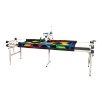
The Quilter's Evolution Elite-Frame is a quilting frame designed to provide a stable and adjustable platform for quilting machines, enabling users to create high-quality quilting projects. This 12-foot frame is part of the Grace Company's product line, known for its quilting accessories.
Function Description:
The primary function of the Quilter's Evolution Elite-Frame is to hold and tension fabric layers (quilt top, batting, and backing) while a quilting machine moves across its surface. This allows for precise and consistent stitching, especially for large quilting projects. The frame is designed to integrate with various quilting machines and accessories, creating a comprehensive quilting setup. It facilitates a "rolling-style" quilting method, where the quilt is advanced by rolling it onto rails as quilting progresses.
Important Technical Specifications:
- Frame Length: 12 feet, indicating its capacity for large quilts.
- Frame Type: Elite-Frame, specifically the Quilter's Evolution Elite 12-Foot model.
- Included Parts and Tools: The frame kit comes in multiple boxes (1, 2, 4, 6, and 7), with boxes 3 and 5 not being used for this specific setup. Key components include:
- Left and Right Side Leg Assemblies (QEF-09-16529, QEF-09-16563)
- Bottom Carriage Assembly (CNT-09-13523)
- Various hardware items: Large Hand Wheel (PLA-05-11550), Large Hand Wheel Knob (PLA-05-11551), Hand Wheel Collar (PLA-05-11552), Quilt-Backing Rail Press-In Cap (QEF-05-16498), Corner Brace A (x2) (QEF-04-15543), Corner Brace B (x2) (QEF-04-15544), Bungee Clamps (4 pack) (ACC-01-10261), Dual-Wheel Channel Lock (x2) (ACC-09-13057).
- Wrenches: Allen Wrenches (6mm, 5mm, 2.5mm, 3mm), T-handle Allen Wrench (4mm), Open End Wrenches (10mm/13mm, 14mm/17mm).
- Bolts and Nuts: SBHCS (M10x55mm, M8x20mm (x4), M8x16mm (x32), M6x20mm (x2), M8x55mm (x4), M10x100mm (x2), M8x16mm (x16)), Washer M8 (x4), Washer M10 (x2), Nylock Nut M10 (x2), Socket CSS (M6x6mm (x16)).
- Table and Rail Components: 5 ft Table with Tracks Assembly (QEF-09-16576), 5 ft Star Rail Assembly (ACC-09-16567), Front Rail Clamp (x2) (QEF-05-16505), 5 ft Round Rail Assembly (x2) (QEF-09-17068), Square Side Rail Assembly - Left (QEF-09-17058), Square Side Rail Assembly - Right (QEF-09-17044), Logo Plate (x2) (ACC-09-16565), Start Right Cloth Leader Set (ACC-01-10750), Frame Reference Card Hook (HDW-03-16369), 38 mm Tube Cap (x2) (BER-05-14868), Take-Up Rail Tower Left (QEF-09-17030), Take-Up Rail Tower Right (QEF-09-17034), 5 ft Table Assembly - 5 ft Extension (QEF-09-17087), Star Rail - 5 ft (QEF-04-15537), Middle Leg (QEF-09-17102), Middle Table Brace (x2) (QEF-04-15545), Round Rail - 5 ft (x2) (CNT-04-1105), 10 ft Plastic Track (PLA-05-10560), Star Rail Coupler (QEF-09-17096), Rail Coupler Assembly (x2) (CNT-09-11865), 2 ft Table Assembly (QEF-09-17151), Star Rail - 2 ft (QEF-04-15538), 2 ft Rail (x2) (MET-04-11397), 12 ft Plastic Track (PLA-05-10561), Track Support Connector (x4) (CNT-04-11041).
- Warranty: One-year limited warranty on all parts, covering manufacturing defects. Excludes misuse, improper storage, improper assembly, loss, natural events, and willful destruction. Parts must be returned prepaid for repair/replacement.
Usage Features:
- Adjustable Frame Height: The frame's legs are adjustable to ensure comfortable prolonged use, allowing users to set the handlebars of their machine or top plate at elbow height. This involves loosening set screws, removing height screws, washers, and nuts, aligning holes based on a height chart (40-48 inches), and then securing them. Middle legs also have adjustable height.
- Track Assembly: Metal tracks are preinstalled but require partial disassembly and reassembly for optimal performance. This involves removing connector bolts, aligning track sections (3-foot and 5-foot metal tracks, 2-foot metal tracks), inserting track support connectors, and securing them with socket CSS screws. Finally, 12 ft plastic tracks are slid into the metal track assemblies.
- Table Installation: The table sections are installed onto the leg assemblies using SBHCS bolts and washers, with middle legs providing additional support. The connections are initially left loose and tightened later to ensure proper alignment.
- Brace Attachment: Corner braces (A and B) and middle table braces are attached to the frame to enhance sturdiness. These are also initially loosely attached and then fully tightened once the frame is aligned.
- Take-Up Rail Towers Installation: These towers hold and position the take-up rail. They are secured into slots on the frame sides with SBHCS bolts and 3-wing knobs, with levers allowing for height adjustment.
- Side Rail Assemblies Installation: Square side rail assemblies (left and right) are attached to the frame using SBHCS bolts. Logo plates are also installed, with the felt side facing the square side rail assemblies.
- Track Attachment and Alignment: The 12 ft track assemblies are placed on the frame, ensuring proper orientation of 3 ft and 2 ft track sections. Connector bolts are used to attach the tracks, with back track bolts tightened first, and front track bolts tightened after the bottom carriage is used to align them.
- Carriage Channel Lock Installation: This lock restricts bottom carriage movement for straight stitching. It involves removing a rear-facing wheel and its screw, installing the dual-wheel channel lock with an SBHCS bolt and the wheel, and then screwing it onto the bottom carriage. The rubber foot of the channel lock can be twisted to extend its reach and ensure firm pressure against the track.
- Machine Channel Lock Installation: Similar to the carriage channel lock, this lock restricts machine movement along the front-to-back axis for horizontal lines. It involves removing an outer wheel and its screw, installing the dual-wheel channel lock with an SBHCS bolt and the wheel, and screwing it onto the machine. The rubber foot can be adjusted.
- Rail Assembly (12 Foot Rails): This involves assembling star rails and round rails from 5 ft and 2 ft sections using star rail couplers and rail coupler assemblies. Screws are tightened counter-clockwise to secure the sections. Quilt-backing rail press-in caps and 38 mm tube caps are installed at the ends.
- Front Rails Installation: The "quilt-backing rail" (star rail) and "quilt-top rail" (round rail) are installed into their respective holders. This involves lifting rail holder tops, removing SBHCS screws, sliding in the rails, and then reattaching the tops. Ratchet levers are used to access screws and secure the rails.
- Take-Up Rail Installation: The 12 ft round rail is inserted through the machine's throat into the take-up rail holders. A hand wheel, hand wheel collar, washer, and M10 x 55 mm SBHCS are attached to the end of the take-up rail.
- Rail Positioning: The take-up rail height is adjusted to be about one-quarter inch above the machine bed, using 3-wing knobs and levers. Front rails are adjusted to accommodate the machine's stroke length and ensure they are square with the frame.
- Bungee Clamps: These clamps hold the sides of the quilt smooth and taut. They are pulled over the side rail, and the clip is slid over the fabric, ensuring the bungee tooth digs into the backing fabric. The bungee cord holder can be slid along the bar to adjust tension.
- Cloth Leader Velcro Installation: Velcro tape is applied to the quilt-top rail and take-up rail, aligning it with the rail holes. Excess Velcro is trimmed.
- Cloth Leaders Installation: Most narrow cloth leaders are attached to the take-up rail Velcro, and medium-width cloth leaders to the quilt-backing rail Velcro. The widest cloth leader is attached to the quilt-top rail Velcro, with the patterned side facing forward.
- Quilt Attachment (Standard Method): This involves folding and marking the centerpoints of the quilt backing, batting, and quilt top. The backing is pinned to the quilt backing rail cloth leader (right side facing wrong side of leader). The backing rail is rolled until the leader cloth is invisible. The batting is pinned to the backing, scrim side down. The quilt top is pinned to the batting, right side up. The quilt top is then pinned to the final cloth leader. Rails are rolled to smooth fabric, and ratchet levers are used to position the quilt for stitching.
- Quilt Attachment (Floating Method): This is a less precise method where one or more layers are not attached to a rail. It involves completing steps 1-14 of the standard method, moving the machine back, opening the ratchet lever on the quilt-backing rail, rolling the hand wheel until the quilt top is about a quarter inch from the needle, closing the ratchet lever, smoothing wrinkles, and pressing front rail clamps onto the quilt-backing rail over the fabric layers.
- Rolling Fabric: Once a quilting zone is complete, bungee clamps are removed, front rail ratchet levers are released, the hand wheel is rotated counter-clockwise to advance the fabric, and ratchet levers are closed. Bungee clamps are reattached, and edges are tacked down to reduce shrinkage.
- Using Channel Locks: Channel locks restrict movement for straight lines. Closing the machine channel lock allows horizontal straight lines, while closing the bottom carriage channel lock allows front-to-back straight lines.
Maintenance Features:
- Frame Leveling: The frame should be tested and re-leveled every six months and whenever it is moved, as uneven floors can cause the machine to drift. This involves adjusting the leveling feet by loosening and tightening nuts.
- Cleaning: The quilting area, frame, carriage tracks, and machine/carriage wheels should be cleaned frequently.
- Thread Tension Testing: A test fabric swatch should be used to test thread tension after every bobbin change to ensure optimal stitching.
- Preventing Channel Lock Loosening: Optional step to tighten hex nuts against the rubber foot and barrel of the channel lock to prevent loosening over time.