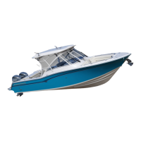
Do you have a question about the Grady-White Boats Express 370 and is the answer not in the manual?
| Cabins | 1 |
|---|---|
| Model | Express 370 |
| Weight | 16, 500 lbs |
| Fuel Capacity | 330 gal |
| Dry Weight w/o Engines | 16, 500 lb |
| Dry Weight w/o Engines (kilograms) | 7484 kg |
| Holding Tank Capacity | 30 gal |
| Holding Tank Capacity (liters) | 114 l |
Details about the compiled information package for boat owners and equipment.
Information regarding the boat's warranty and the dealer's obligations.
Outlines the duties and obligations of the Grady-White boat owner.
Explanation of safety labels used throughout the manual to denote hazards.
Lists minimum required and additional recommended safety equipment for boating.
Details on boat registration requirements and the Hull Identification Number (HIN).
Operation of the emergency stop switch and general emergency preparedness.
Essential precautions and tips for safe boating practices.
Information on NMMA and ABYC certifications ensuring safety and quality.
Guidance on safe loading and awareness of carbon monoxide hazards.
Recommendations for boating classes and reading materials for enhanced knowledge.
Safe practices and precautions for fueling the boat.
Operation of the fuel select valve and EPA compliance standards.
Rules regarding discharge of substances and disposal of garbage.
Guidance on trailering the boat and pre-departure checklists.
Instructions for maneuvering near docks, anchoring, and towing.
Precautions and techniques for operating in shallow water.
General boat handling tips and specifics for twin/triple engine boats.
Definitions of commonly used nautical terms for clarity.
Factors influencing boat performance like engine tuning and weather.
Impact of engine condition, load, and trim on overall performance.
Effect of hull growth and proper propeller selection on boat speed.
Details on engine warranty and operation of mechanical/hydraulic steering.
Explanation of how to operate the throttle and gear shift controls.
Overview of the Yamaha instrumentation panel and its features.
Detailed functions of the Command Link Plus display for boat data.
Information on displays used for triple engine configurations.
Explains how to read engine RPM via the digital tachometer.
Describes the integrated boat control system for enhanced maneuverability.
Details the location and function of various accessory switches.
Factors affecting maintenance needs and general upkeep advice.
Guidance on cleaning, polishing, and waxing the boat's gel coat.
Procedures for repairing gel coat and applying anti-fouling bottom paint.
Maintenance for canvas, vinyl, snaps, and zippers.
Cleaning instructions for upholstery, plastic, and rubber components.
Proper mounting of hardware and maintenance of anodized aluminum parts.
Procedures for maintaining the boat's fuel system.
Maintenance for fuel tank areas, shower sumps, and battery systems.
Information on the serviceability and replacement of LED lighting fixtures.
Wiring color codes and fuse/breaker information for DC accessories.
Overview of routine maintenance required before and during storage.
Guidelines for safely storing the boat, including lifting and support.
Steps for cleaning, lubricating, and draining water systems for storage.
Winterizing the head system and preparing batteries for storage.
Winterizing engines, fuel systems, and using a storage checklist.
Essential checks before launching and after the storage period.
Technical specifications and available optional features for the Express 370.
A list of various accessories and optional equipment available for the boat.
How to operate the standard features and systems on the boat.
Details the layout and function of the accessory switch panels.
Description of the AC/DC electrical panel and power distribution methods.
Explanation of the operation of various AC-powered accessories.
Explanation of the operation of various DC-powered accessories.
Location and purpose of the auxiliary DC fuse panel.
Operation of 12V accessory outlets and the air conditioning system.
Operation details for pumps, chargers, and battery select switches.
Information on bilge pump operation, locations, and bow thruster use.
Operation of cabin lighting and the cockpit cooler refrigeration system.
Operation of cockpit showers, compass, freshwater, and washdown systems.
Guide to generator operation, control panel, and accessory amperage needs.
Procedures for stopping the generator and function of blower/CO detectors.
Usage limits for hardtop, head shower operation, and bilge alarm.
Operation of livewell, main breaker, microwave, and AC outlets.
Details on power steering, washdown, and refrigerator/ice maker.
Operation of seacocks and procedures for connecting shore power.
Using shore water and operating the shower sump pump.
Instructions for operating the stereo, stove, and trim tab systems.
Information on trim tab pump, TV/DVD, and VacuFlush head systems.
Procedures for head discharge, deck pump-out, and water heater operation.
Operation guides for optional grill, outriggers, and satellite radio.
Diagram illustrating the boat's fuel system layout.
Diagram showing the layout of the cabin air conditioning system.
Diagram showing the layout of the helm air conditioning system.
Diagram illustrating the cockpit cooler system layout.
Diagram showing the layout of the livewell and raw water washdown systems.
Diagram illustrating the VacuFlush head system components and routing.
Diagram showing the layout of the pressurized freshwater system.
Diagram indicating locations of access plates and hull rigging tubes.
Diagram illustrating the location of liner rigging tubes within the boat.
Diagram showing the placement of important safety labels on the boat.
Diagram detailing the location and identification of thru-hull fittings.
Diagram showing the layout of the generator system components.
Diagram illustrating the layout of bow thruster and power assist systems.
Diagram showing the installation of accessories on the boat's hardtop.
Diagram showing the layout of the boat's stereo system components.
Diagram indicating the locations of all 12V DC accessories.
Diagram indicating the locations of all 120V AC accessories.
Detailed wiring diagram for the 12V DC system with dual engines.
Wiring diagram for 12V DC system with triple engines and Helm Master option.
Wiring diagram for 12V DC system with triple engines and power assist.
Overall one-line diagram for the boat's AC electrical system.
Wiring diagram for the 120V AC air conditioning and cockpit cooler systems.
Wiring diagram for 120V AC air conditioning, coolers, and grill.
Wiring diagram for the 12V DC accessory switch panel.
Wiring diagram for the 12V DC cabin switch panel.
Wiring diagram for the 12V DC cockpit switch panel.
Wiring diagram for the 12V DC cabin lighting circuits.
Wiring diagram for the 12V DC fuse block.
Wiring diagram for the 12V DC anchor windlass system.
Wiring diagram for electrical components on the boat's hardtop.
Wiring diagram for the 12V DC trim tab system.
Wiring diagram for the 12V DC ignition circuit and trim systems.
Wiring diagram for the 12V DC high bilge water alarm system.
Wiring diagram for the 12V DC stereo system and speakers.
Wiring diagram for the 12V DC TV and DVD player system.
Details on plug types, sizes, and their connections for electrical systems.
Comprehensive 12V DC electrical diagram for dual engine configurations.
12V DC electrical diagram for triple engines with Helm Master option.
12V DC electrical diagram for triple engines with power assist option.
Comprehensive diagram of the 120V AC electrical system.
Mandatory steps for registering boat purchases for warranty purposes.
Details of the transferable structural hull warranty coverage.
Coverage details for defects in material and workmanship within one year.
List of conditions and damages not covered by the boat's warranty.
Step-by-step instructions for initiating and processing a warranty claim.


 Loading...