7
This faucet complies with NSF61/9, ASME/ANSI A112.18.1
and CSA B 125 Standards.
Este grifo se encuentra conforme con losestandares de NSF61/9,
de ASME/ANSI A112.18.1 y de CSA B 125.
Installation Instructions Instrucciones de Instalación
THERMOSTATIC SET
CONJUNTO TERMOSTÁTICO
7
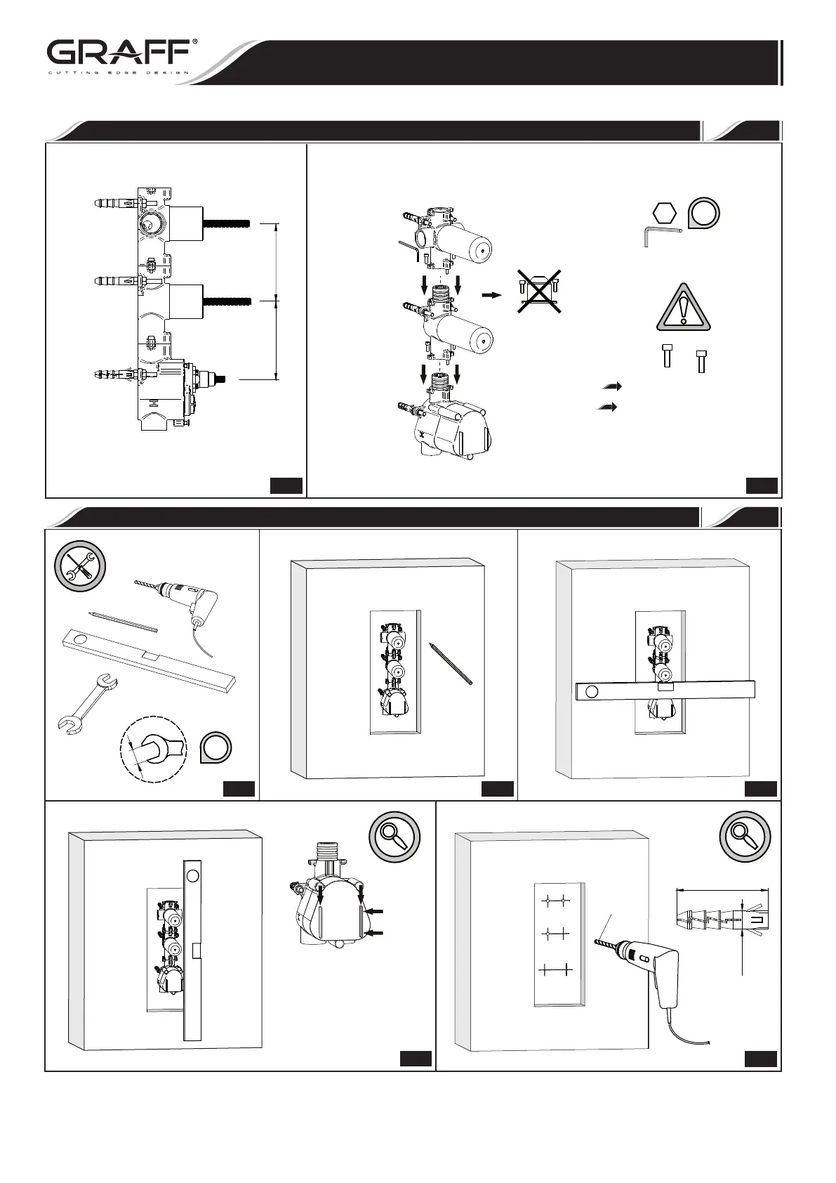
THE ASSEMBLY OF THERMOSTAT
MONTAJE DE TERMÓSTATO
3
i
Mount the individual elements
using two bolts M4
Montar los respectivos elementos
con el empleo de dos tornillos M4
2.1 2.2
3-15/16”
(100 mm)
3-15/16”
(100 mm)
IOG 5013.20
8
THE INSTALLATION OF THERMOSTAT
INSTALACIÓN DE TERMÓSTATO
3.1
3/8”
(10)
i
Ø
3/8”
(10 mm)
1-15/16”
(50 mm)
Ø3/8”
(10mm)
3.2
3.3
3.4
3.5
Rev. 3 October 2018