3
This faucet complies with NSF61/9, ASME/ANSI A112.18.1
and CSA B 125 Standards.
Este grifo se encuentra conforme con losestandares de NSF61/9,
de ASME/ANSI A112.18.1 y de CSA B 125.
Installation Instructions Instrucciones de Instalación
IOG 5207.70
Rev. 1 June 2019
2.1
A
P1
Supply system
Instalación alimentadora
Finished wall
Pared de acabado
11
9
1
K2
A
~
ESPANOL
ENGLISH
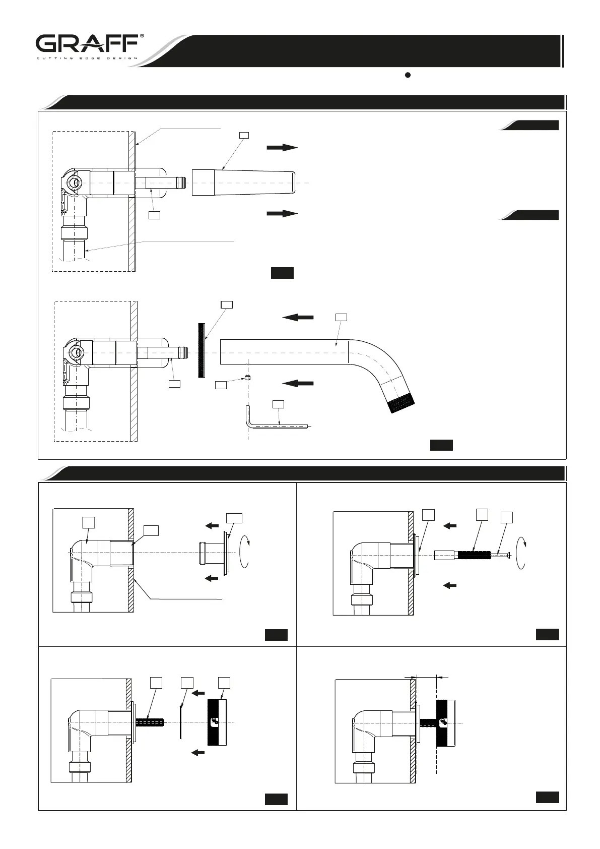
Take the asseembly cover (P1) off the spout nozzle (A) .
Slide the spout base (9) onto the spout nozzle (A).
Carefully slide the spout tip (1) onto the spout nozzle, while
making rotary motions with the spout. Make sure if the
O-ring seals are correctly placed in grooves of the spout
nozzle.
Set the spout (1) in proper position and secure it with screw
(11). Use the Allen key attached.
1.
2.
3.
4.
Quite la chapa de montaje (P1) de la válvula del caño (A) .
Coloque el florón para caño (9) en la válvula del caño (A).
Coloque con cuidado la punta del caño en la válvula del caño
(1) haciendo movimientos de rotación del caño. Asegúrese
que los selladores de anillo están correctamente posicio-
nados en las ranuras de la válvula del caño.
Coloque el caño (1)en la posición adecuada y apriételo con
tornillo (11). Utilice la llave hexagonal proporcionada.
1.
2.
3.
4.
See figs.2.1-2.2
Verlaimagen2.1-2.2
2.2
TWO HANDLE WALL-MOUNT LAVATORY FAUCET
GRIFO DE DOS MANILLAS MONTADOS EN LA PARED
SPOUT INSTALLATION • INSTALACIÓN DEL CAÑO
HANDLES INSTALLATION • INSTALACIÓN DE LAS MANILLAS
A
17
Finished wall
Acabado de la pared
16
15
17
17 7
5
C
H
3.1
3.2
3.3
3.4
 Loading...