~
3
~ ~
4
~
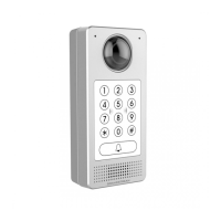
Step 3:
Make sure the ”Back Cover Frame” is in place, the wired back
cover panel is good. Flush the back cover panel piece with the
whole back surface of device, tighten it using the screws provided.
Step 4:
Take out the two preinstalled anti-tamper screws using the hex key
provided. Carefully align the GDS3712 to the metal bracket on
wall, press and pull the GDS3712 down to the right position.
Step 5:
Install the two anti-tamper screws back using the hex key provided
(do NOT over tighten the screws). Cover the two screw holes on
the bottom of “Back Cover Frame” piece using the two silicon
plugs provided. Final check and nish the installation.
In-Wall (Embedded) Mounting
Please refer to the “In-Wall (Embedded) Mouting Kit”,
which can be purchased separately from Grandstream.
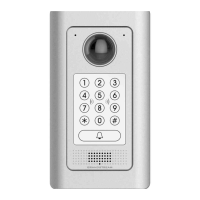
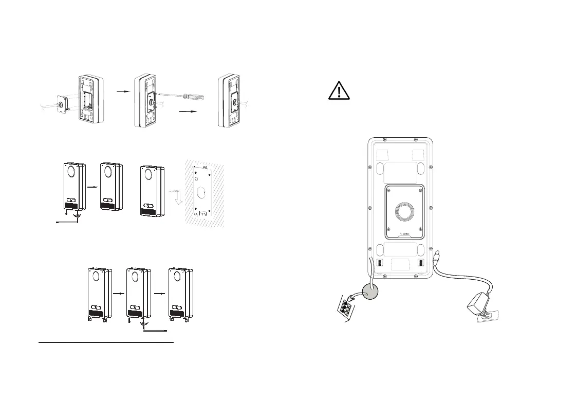
CONNECTING THE GDS3712
Refer to the illustration below and follow the instructions
on the next page.
Note:
Choose Option A if using PoE switch (Class 3);
OR: Option B if using 3rd party power source.
Option B:
DC12V, 1A minimum
Power Source
(not provided)
Option A:
RJ45 Ethernet Cable to (Class 3) Power over Ethernet
(PoE) Switch.
Network Port
Power Port
12V
POWER OFF GDS3712 when connecting wires or
inserting/removing the back cover panel piece!
 Loading...