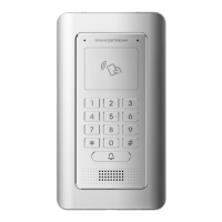
EasyManuals Logo
Home>Grandstream Networks>Intercom System>GDS3712

Grandstream Networks GDS3712 User Manual

Grandstream Networks GDS3712
85 pages
To Next Page IconTo Next Page
To Previous Page IconTo Previous Page
Page #8 background imageLoading...
Page #8 background image
J2 (Basic)
3.81mm
TX+ Ethernet
PoE 802.3af
Class 3,
12.95W
Orange / White Data
TX- Orange
RX+ Green / White
RX- Green
PoE_SP2 Blue + Blue/White Please twist these two
wires together and
connect to SP1, SP2
respectively even the PoE
NOT used.
PoE_SP1 Brown + Brown/White
RS485_B
RS485
RS485_A
GND
Power Supply DC 12V, 1A Minimum
12V
J3 (Advanced)
3.81mm
GND Alarm GND
ALARM1_IN+
Alarm In Vin<15V
ALARM1_IN-
ALARM2_IN+
ALARM2_IN-
NO1
Alarm Out Relay: 30VDC/2A; 125VAC/0.5A
COM1
NO2
Electric Lock
For "Fail Secure" (Locked when Power Lost) Strike, connect
COM2 & NO2.
For "Fail Safe" (Open when No Power) Magnetic Lock,
connect COM2 & NC2.
Relay: 30VDC/2A; 125VAC/0.5A
COM2
NC2
J4 (Special)
2.0mm
GND
Wiegand
Power GND
Black
Both Input and Output
MUST be connected
WG_D1_OUT
Wiegand
Output Signal
Orange
GDS3705 function as
Output of Card Reader,
Connect Pin 1, 2, 3
WG_D0_OUT Brown
LED
Wiegand
Output LED
Signal
Blue
For External Card Reader;
Or GDS3705 as Receiver
Only
WG_D1_IN Wiegand Input
Signal
White For External Card Reader
Connect Pin 1,4,5,6,7,8

Other manuals for Grandstream Networks GDS3712

Questions and Answers:

Question and Answer IconNeed help?

Do you have a question about the Grandstream Networks GDS3712 and is the answer not in the manual?

Grandstream Networks GDS3712 Specifications

General IconGeneral
BrandGrandstream Networks
ModelGDS3712
CategoryIntercom System
LanguageEnglish

Related product manuals