17
STEP 4: Optional Mid Boost Switch
Install the switch in a new hole in the pick guard (or control plate).
Plug the Six-Pin connector (blue, purple, yellow, green and black wires) from
the switch into the MID, FAAS, VOL and MAG pins of the Acousti-Phonic Intel-
ligent Pre-amp.
Cut the VOL (yellow) wire to length and solder to the centre contact of the
GHOST volume pot (Diagram 10). Cut the ground (black) wire to length and
solder to the outer casing of the GHOST volume pot. Solder the wire from the
centre of the switch to the top of the GHOST volume control.
•
•
•
If you are NOT installing the optional Mid Boost Switch, skip to STEP 5, page
18. The Acousti-Phonic Intelligent Pre-amp processes the signal from the GHOST
pickups to produce the GHOST acoustic tone. This is the signal from the GHOST
output that normally connects to the top contact of the volume control.
A second sound is available from the Acousti-Phonic Intelligent Pre-amp. The
signal from the Mid/Dark output boosts the mids, lowers the highs and lows
and produces a new tone. You can t a switch to allow you to switch instantly
between the GHOST and Mid Boost sounds.
A pre-wired switch assembly is available:
Mid/Dark Switch Assembly part number PE 0106-00
To install and wire the Mid/Dark Switch Assembly:
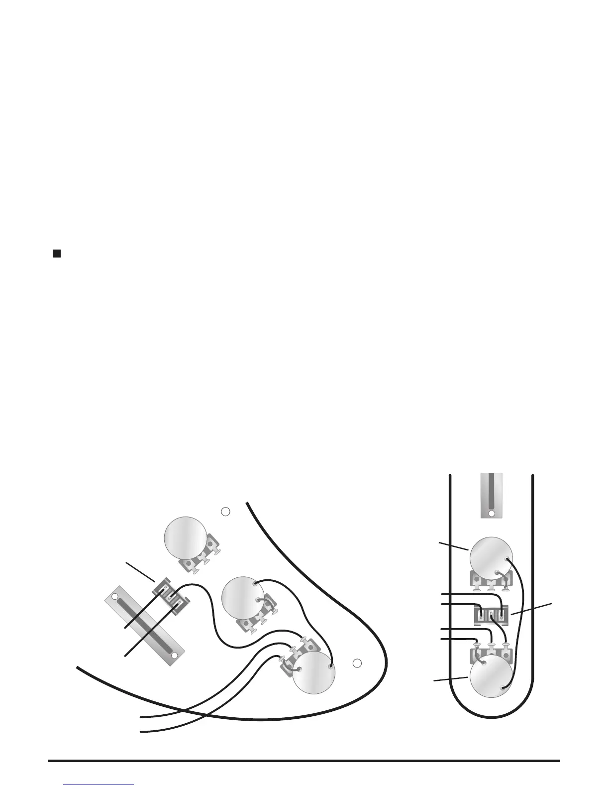
For clarity the wiring diagrams below show only the new wires.
Strat Style Instruments Tele Style Instruments
Mid
Boost
Magnetic
Volume
Magnetic
Tone
GHOST
Volume
Magnetic
Volume
GHOST
Volume
Mid
Boost
GHOST (Purple)
MID (Blue)
VOL (Yellow)
GND (Black)
GHOST (Purple)
MID (Blue)
VOL (Yellow)
GND (Black)
Diagram 10.
 Loading...