15
drilling holes in working modes: with impact, rotation only, chasing or surface processing of materials such
as concrete, stone, brick etc. Range of use covers repair and building works, woodworking and any work
from the scope of individual, amateur activities (tinkering).
Use the power tool in accordance with the manufacturer’s instructions only.
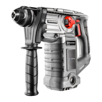
DESCRIPTION OF DRAWING PAGES
Below enumeration refers to the device elements depicted on the drawing pages of this manual.
SDS-Plus chuck1.
Fixing sleeve2.
Direction selector switch3.
Switch lock button4.
Switch5.
Operation mode switch6.
Additional handle7.
Depth gauge rod 8.
Lock button for depth gauge rod9.
* Dierences may appear between the product and drawing.
MEANING OF SYMBOLS
CAUTION
WARNING
ASSEMBLY / SETTINGS
INFORMATION
EQUIPMENT AND ACCESSORIES
Additional handle - 1 pce1.
Depth gauge rod - 1 pce2.
Drill chuck - 1 pce3.
Drill chuck adapter - 1 pce4.
Drills - 1 pce 5.
Carrying case - 1 pce6.
PREPARATION FOR OPERATION
INSTALLATION OF ADDITIONAL HANDLE
Due to safety issues, always use additional handle when operating the rotary hammer. It can be xed
in any position on the xing cylindrical section.
● Turn lower part of the additional handle (7) counter-clockwise to loosen.
Slide the additional handle collar ( ● 7) over cylindrical section of the rotary hammer body.
Turn to the most comfortable position for the work at hand. ●
Turn lower part of the additional handle ( ● 7) clockwise to securely lock in selected position.
INSTALLATION OF DEPTH GAUGE ROD
Depth gauge rod (8) is used to limit the depth of drill penetration in material.
● Press the lock button for depth gauge rod (9) (g. A).
Slide the depth gauge rod ( ● 8) into the hole in the additional handle collar (7).
Release the lock button for depth gauge rod ( ● 9) to lock in desired position.
Notches on the depth gauge rod (8) should be in level plane, perpendicular to the additional handle (7).
This position allows to optimally secure lock of the depth gauge rod.