17
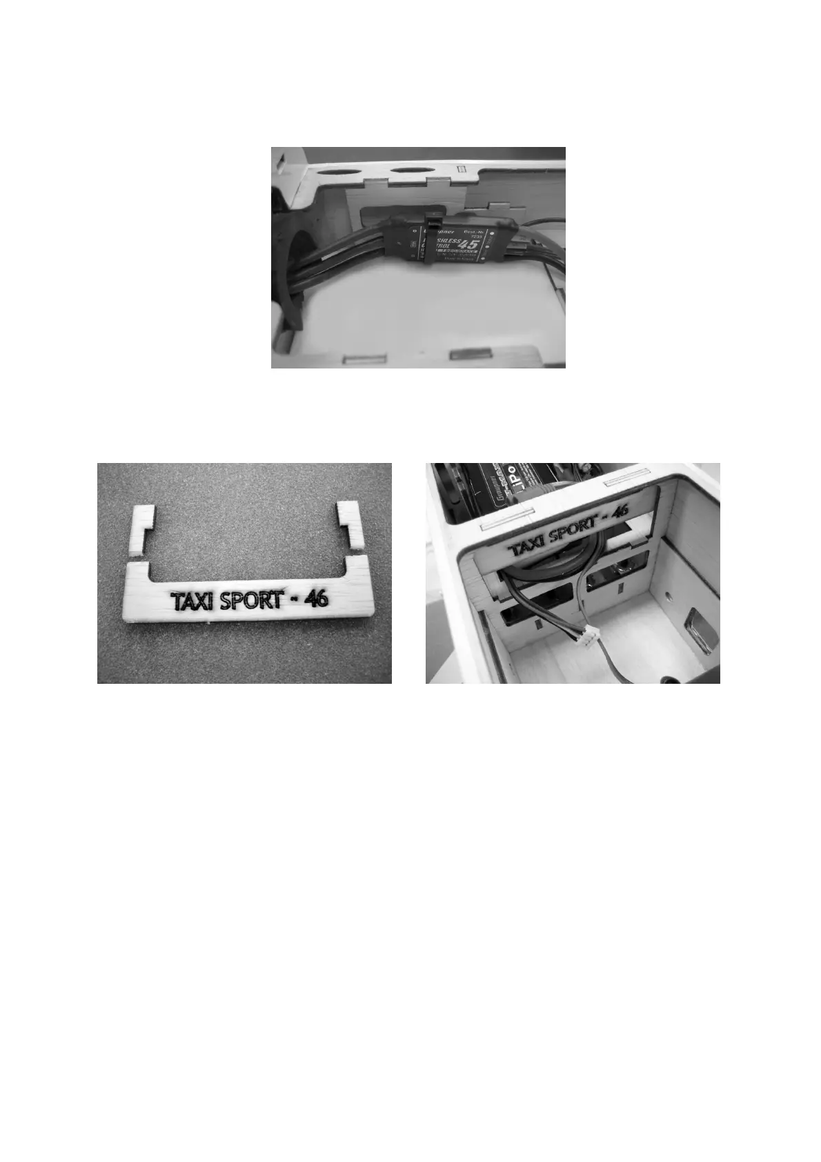
The speed controller is fixed to the right-hand fuselage side using a single cable tie,
as shown in the photo below.
Cut down the fueltank support as shown in the picture to form the rear support for the
flight battery, which prevents the pack sliding aft. Glue the support to the former.
The flight battery is held down by a block of foam glued to the fuselage hatch. The
foam, Order No. 2905.25, is an ideal material for this.
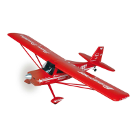
Assembling the TAXI SPORT II
We recommend that you permanently connect a suppressor filter, Order No. 1040, to
receiver sockets 2 and 5, as this makes it easier to connect the aileron servos when
rigging the model. Wrap the receiver battery in foam and secure it in the fuselage in
such a way that it cannot possibly shift. Connect the two aileron servos to the
extension leads, then connect the wing panels using the aluminium joiner tube before
attaching the wing to the fuselage using the four plastic screws supplied in the kit.
Balancing the TAXI SPORT II
Assemble the aircraft completely, and support it on both sides of the fuselage at a
point around 90 mm aft of the wing root leading edge. If the model is balanced
correctly, it will hang level, ideally with the nose inclined slightly down.
If necessary, correct the model’s Centre of Gravity by re-positioning the battery, or by
permanently installing nose or tail ballast.
Before flying the aircraft, set the transmitter trims to centre and ensure that all the
control surfaces are also exactly at centre (neutral).
 Loading...