GB - 11
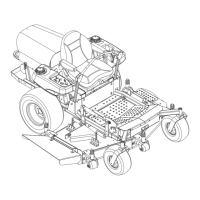
UNIT ASSEMBLY
Package Contents:
Unit, Mower Deck and Literature Pack
Preparation Checklist
Refer to the Owner/Operator manual as required.
1. Unpack Unit - Remove shrink wrap and packaging
materials.
2. Remove Unit From Container - Open Bypass Valves
(dump valves) (See
Moving the Unit with the Engine
Off
on page 14).
Push unit from container onto a level surface. Close
the dump valves.
3. Tires - Adjust tire pressure for front tires: 20-25 PSI
(138-172 kN/m
2
), rear tires: 12-15 PSI
(83-103 kN/m
2
).
4. Position and Attach Seat - Remove nuts from seat
studs in hood frame. Lift and rotate seat onto hood
frame. Secure with nuts.
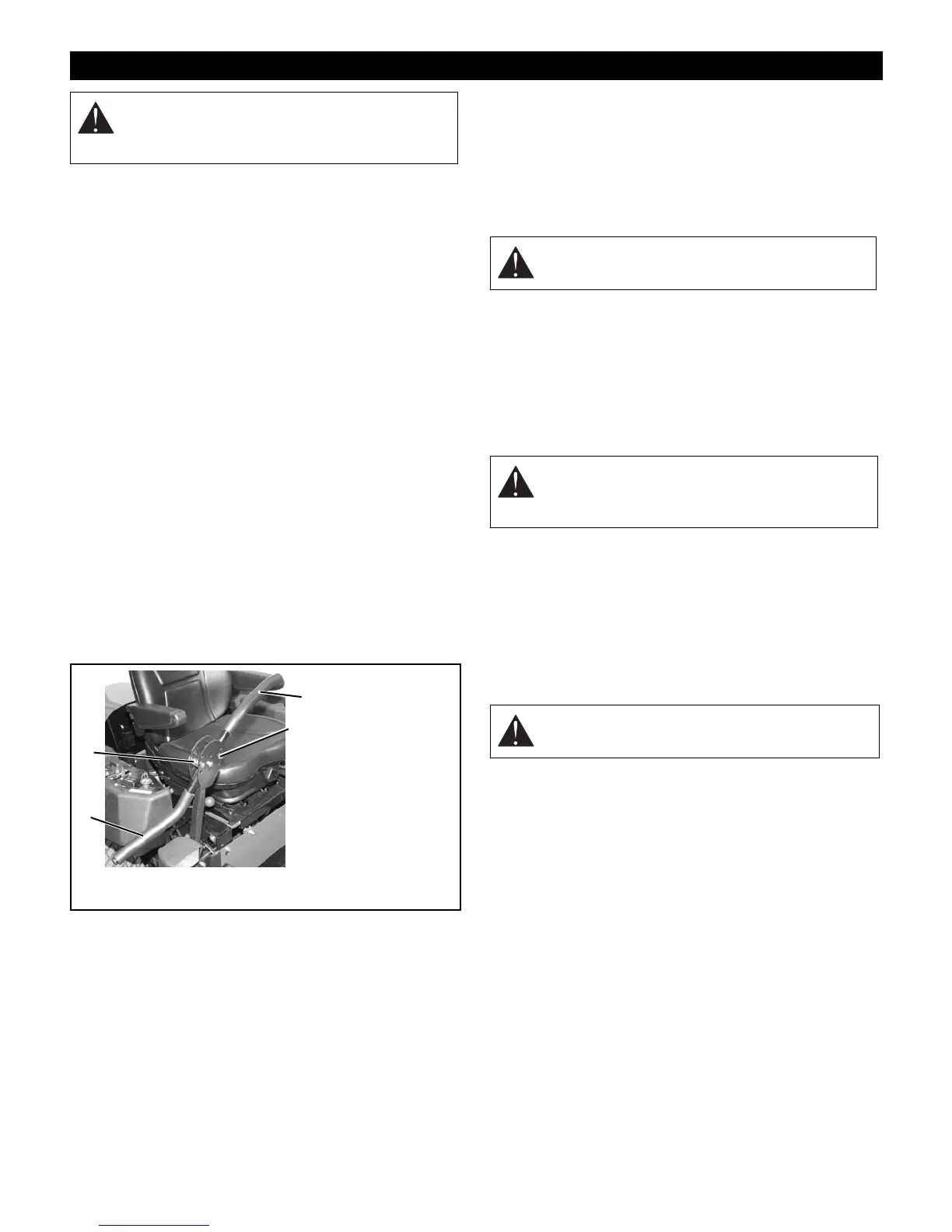
5. Position Steering Levers - Remove bolts and
spacers from steering rod. Flip the steering levers
into operating position. Reinstall spacers, bolts and
nuts. Tighten hardware securely. See Figure 4.
6. Battery - Remove battery from unit and charge (See
Battery
on page 19).
7. Check Engine Crankcase - To access engine, open
hood. Check and add oil if needed. See Engine
Manual for specifications.
8. 60" and 72" Decks - Remove, reverse, and reinstall
discharge chute and mounting bracket.
9. Fill Engine Fuel Tank - Add clean fuel to the fuel
tank.
IMPORTANT:
Refer to Engine Manual for fuel type.
10. Hardware - Check for loose hardware.
11. Check Safety Interlock System - Check to see that
the interlock system operates correctly (See
Safety
Interlock System
on page 12).
12. Lubrication - Lubricate all fittings per maintenance
label under seat and check hydrostat oil level (See
Lubricate Unit
on page 20).
13. Level Deck - Check unit to assure deck level set at
factory has been maintained (See
Leveling the
Mower Deck
on page 24).
14. Check Function of all Controls - Ensure unit runs
and performs properly.
ASSEMBLY
WARNING:
AVOID INJURY. Read and
understand entire
Safety
section before
proceeding.
1. Steering Lever in
Shipping Position
2. Spacers and
Hardware
3. Steering Lever in
Operation
Position
OF3520
Figure 4
1
2
3
2
WARNING:
Discharge chute must pivot freely.
DO NOT overtighten the pivot bolts.
WARNING:
FAILURE OF INTERLOCK
together with improper operation can result in
severe personal injury.
WARNING:
FAILURE OF CONTROLS could
result in death or serious injury.