GB - 13
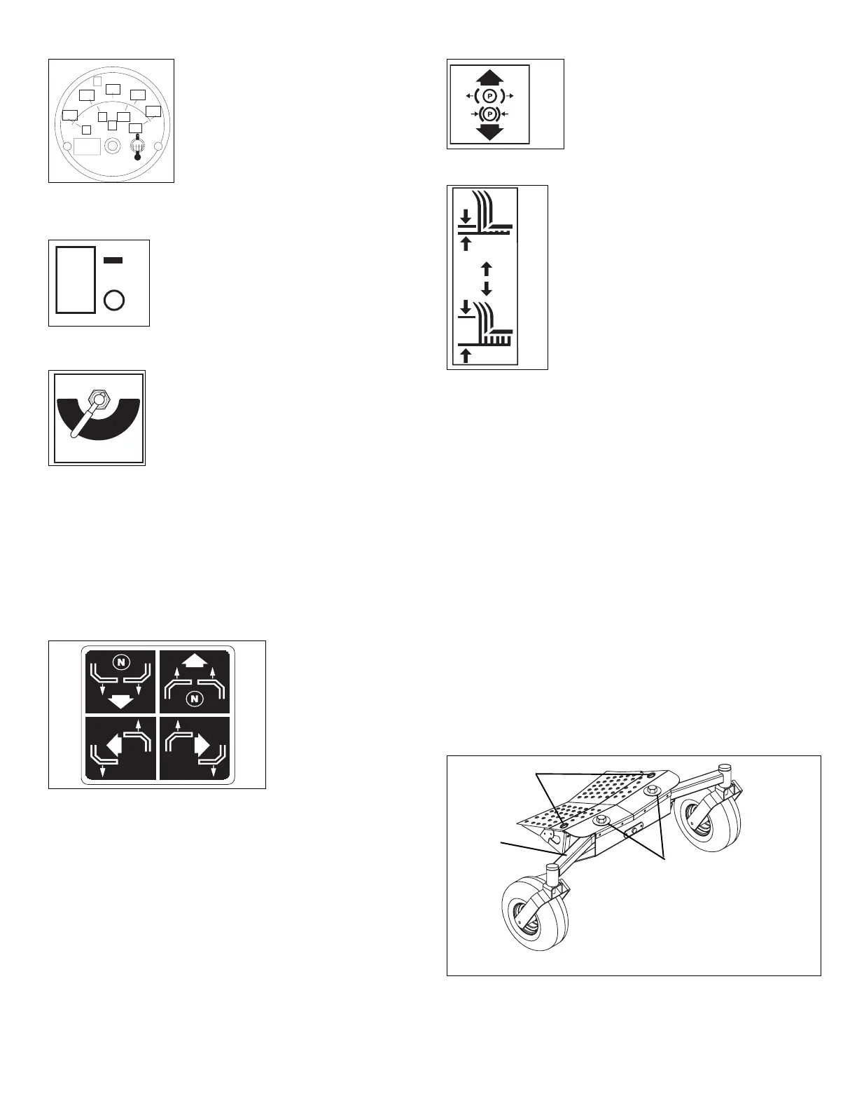
Water Temperature Gauge
Indicates temperature of coolant.
Refer to Engine Manual for normal
operating range.
Headlight Switch
Turns headlights on and off.
Off (1)
On (2)
Fuel Valve
Controls fuel flow from left tank (1) or right
tank (2).
NOTE: There is no Off (3) position.
Fuel/Water Separator Light (992060, 061, 318, 319)
Indicates when fuel/water separator filter needs to be
replaced (refer to Engine Manual).
Battery Light
Lights up when starting engine and indicates that battery has
a full charge. If battery light does not light up, battery needs
charging (see Charging the Battery on page 18).
Steering Levers
Controls speed,
directional control, and
stopping unit.
• Reverse (1) – Pull
both steering levers
backward.
• Forward (2) – Push
both steering levers
forward.
• Left (3) – Pull left steering lever back or push right
steering lever forward or a combination of both.
• Right (4) – Pull right steering lever back or push left
steering lever forward or a combination of both.
To stop, return both steering levers to neutral.
NOTE: Steering levers are mechanically locked in neutral
whenever parking brake is engaged.
NOTE: Aggressive turning can scuff or damage lawns.
ALWAYS keep both wheels rotating when making sharp
turns. DO NOT make turns with inside wheel completely
stopped. To obtain minimum turning radius, slowly reverse
inside wheel while moving outside wheel slowly forward.
Parking Brake Lever
Engages (2) and disengages (1)
parking brake.
Mower Lift Lever
Raises and lowers mower deck.
To lower (1) – Move mower lift lever
forward.
To raise (2) – Move mower lift lever
rearward.
Cylinder Stops
Ensures the same cutting height after raising mower deck to
clear an obstacle. Cylinder stops are stored on a post behind
hydraulic lift cylinder and come in two sizes: 11/32 in. and
11/16 in. (8.73 mm and 17.5 mm).
1. Remove cylinder stops from post and snap onto lift
cylinder rod.
2. Push lift lever forward until cylinder rests against
cylinder stops.
Seat Adjustment Lever
Pull lever out and slide seat to desired position. Release
lever to lock seat into position.
Seat Suspension Adjustment Knob
To make seat more firm turn knob clockwise. To make seat
less firm turn knob counterclockwise.
Axle Locks
For a solid front axle, install axle locks on front axle. For a
pivoting front axle, remove axle locks from front axle and
store on unit (figure 5).
°F
170
195
220
280
100
40
80 100
140
WATER
TEMP
°C
OF330
OF3313
2
1
RIGHT
TANK
LEFT
TANK
OFF
OF1881
1
2
3
077348A
1
3
2
4
OF174
1
2
OF1700
1
2
OF3308
1
2
3
Figure 5
1. Axle Lock Storage
2. Axle Locks Installed
3. Front Axle



 To Next Page