DISCUSSION
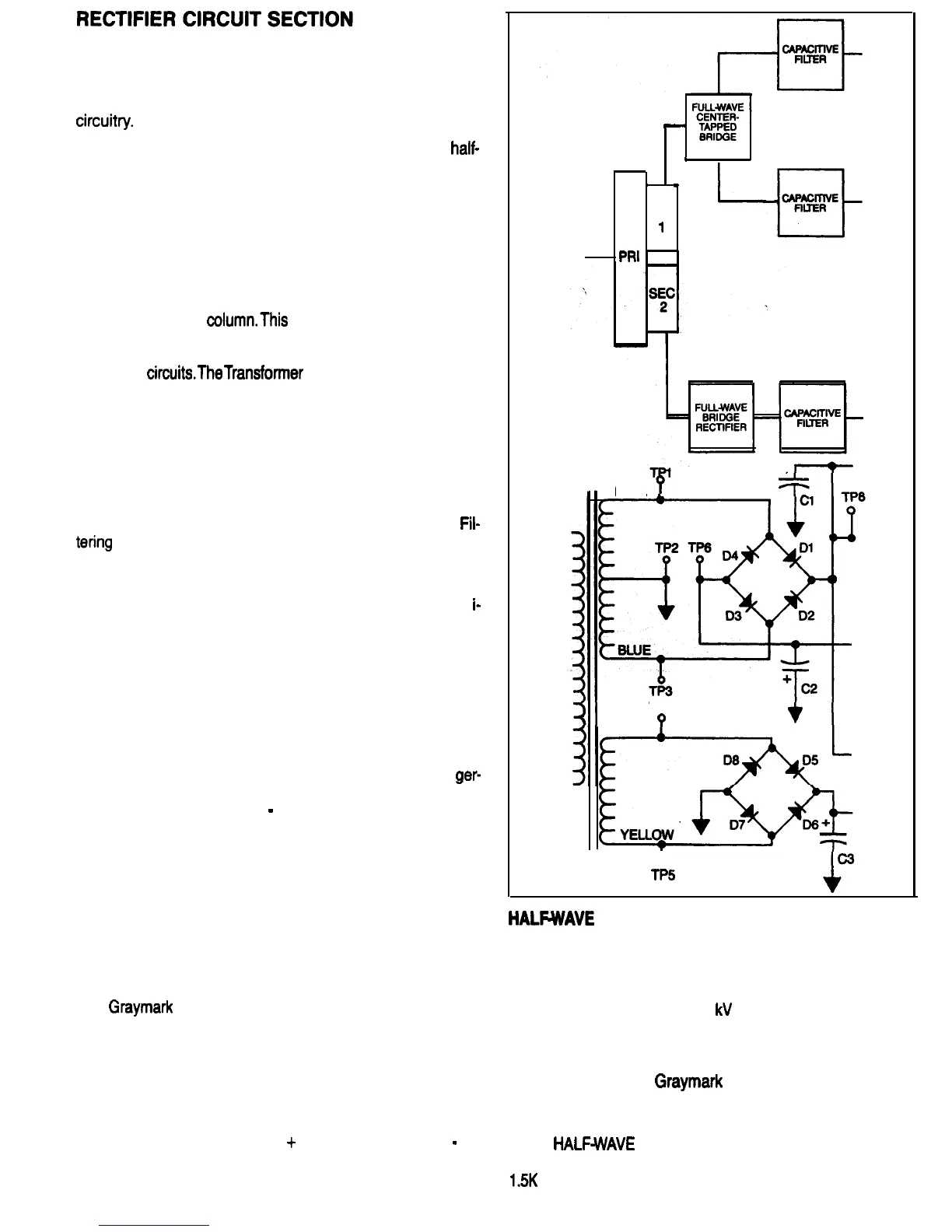
Figure 36 is a partial block diagram and schematic of the
808 Power Supply, showing the rectifiers and associated
circuitv.
There are three basic types of rectifier circuits: the
half-
wave, the full-wave center-tapped, and the full-wave
bridge. Each of these rectifier circuits uses a different num-
ber of diodes and requires a transformer winding with a dif-
ferent rating. Figures 36A and 37 identify some of the differ-
ences between these three types of circuits.
The first column in Fig. 37 contains the three types of recti-
fier circuits. The number of diodes used by each circuit is
listed in the second column. The average diode current is
shown in the third
column.This
value has significance be-
cause diodes with a higher current rating are required for
half-wave circuits, as compared to those required by the
other two
circuits.TheTransformer
Power Rating column is
also important, since each type of circuit requires a trans-
former or a transformer winding with a different power ca-
pacity. And, the larger the power capacity required, the
greater the size and the cost of the transformer.
The Ripple column refers to the percentage of ac voltage
contained in the DC output of the rectifier circuit. A de-
crease in the percentage of ripple offers a corresponding
decrease in the amount of capacitance required in the
Fil-
tering
Stage. Since lower value capacitors are smaller in
size and cost less, a low percentage of ripple from the recti-
fier circuit is desirable.
Finally, the Conversion Efficiency column indicates the eff
i-
ciency of each Rectifier Circuit in converting alternating
current to direct current. Notice that the full-wave rectifier
circuits are twice as efficient as the half wave circuit.
The heart of the rectifier circuit is the diode. Most diodes
are made from silicon or germanium, both of which are
semiconductors. Silicon is used for almost all diodes used
in power supply rectifier circuits, as it is capable of operat-
ing a higher temperature than germanium. For a given size
of device, a silicon diode can pass more current than a
ger-
manium diode. A diode is a component which will allow cur-
rent to flow in one direction
-
from cathode to anode. Refer
to Fig. 38.
Alternating current flows first in one direction, then the op-
posite direction, then reverses direction again. This alter-
nating action occurs continuously. Direct current, on the
other hand, flows in only one direction. A diode can be put
in the path of an alternating current to block the current flow
in one direction and permit the current flow in the opposite
direction. It is in this manner that alternating current is recti-
fied or converted into pulsating direct current.
The
Graymark
Model 808 Power Supply uses four silicon
diodes in a full-wave bridge rectifier circuit, and four more
silicon diodes in a center-tapped full-wave bridge
rectifier circuit.
The center-tapped full-wave rectifier circuit combines fea-
tures of the center-tapped full-wave and the full-wave
bridge rectifier circuits. It is used in the 808 Power Supply
to provide power for the 0 to
+
15 Volt and the 0 to
-
15
Volt outputs. Before going on to the FILTERING section,
you will build and test four types of rectifier circuits.
-
POWER
TRANSFORMER
’
1
4
SEC
1
PRI
.
RECTIFIER
A
BLUE
TP4
?
Tl
A
TP5
FIG. 36
HALFWAVE
RECTIFIERS
DISCUSSION
Half-wave rectifier circuits are sometimes used where the
current requirements are low, in the order of 10 to 100
microamps, and voltages of 1
kV
(1000 Volts) or higher are
needed. Photomultiplier tubes and Ion chambers, which
are used to detect and measure radiation, are examples of
devices requiring this type of DC power. Utility power sup-
plies, such as your
Graymark
808, which are generally
used to power solid state analog and digital devices, do
not usually use half-wave rectifier circuits.
In the
HALFWAVE
RECTIFIER TEST, you will be viewing
the output of a half-wave rectifier on an oscilloscope. A
1.5K
Ohm resistor (Rl 1) is connected across the output of
22

 Loading...