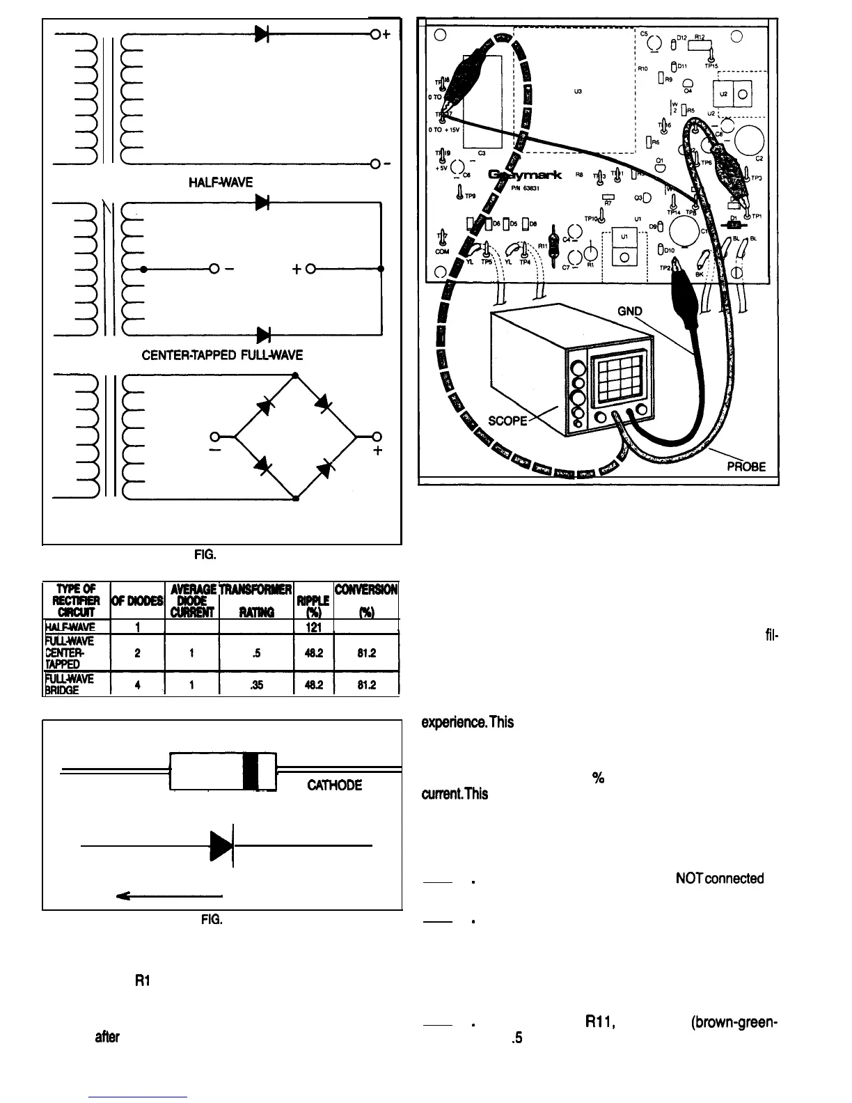
l-lALFwAVE
CENTERTAPPED
FULLWAVE
Without it, dangerously high voltages could remain present
FULL WAVE BRIDGE
long after the input power has been turned off or
TYPES OF RECTIFIER CIRCUITS
disconnected.
FIG.
36A
SIGNIFICANT RECTIFIER CIRCUIT CHARACTERISTICS
NUMBER
AVERME
TRANBFDRMER
coNvERsloN
ofDlooEB~
POWER
RiPPLE
EFFICIENCY
REQUIRED
CuRRENr
Rmm
,
1
2
1
121
4Q.6
FIG. 37
DIODE
,
1
,
ANODE CATtiODE
ANODE
CATHODE
-
CURRENT FLOW
FIG.
36
the rectifier circuitry. Figure 43 is a schematic of this circuit.
Without this resistor, stray circuit capacitances could distort
the waveform displayed on the scope. In the completed
Power Supply
Rl
1 serves as a bleeder resistor.
One of the functions of a bleeder resistor is to discharge
or “bleed off” the electrical energy remaining in the filter ca-
pacitors
atier
the power supply is turned off. In high voltage
supplies, the bleeder resistor is an important safety device.
FIG. 39
The output voltages of the Model 808 Triple Power Supply
are not high enough to be hazardous to the person using
it, but it is disconcerting when a power supply that has been
turned off earlier generates a spark if an output is acciden-
tally shorted. In the 808 Power Supply, bleeder resistors,
along with the voltage regulators, serve to discharge the
fil-
ter capacitors within seconds after the input power has
been switched off or disconnected.
When you are building your 808, you will be instructed to
install some components long before they are used in an
experience.This
is to provide a discharge path for the filter
capacitors before the voltage regulators are installed.
In unregulated power supplies the bleeder resistor is is
often designed to draw 10
%
or more of the rated output
current.This
is to improve the voltage regulation of the sup-
ply under changing load conditions.
CONSTRUCTION
Refer to Fig. 39 for the following steps.
1
.
2
.
3
.
Be sure the 808 power plug is
NOTconnected
to
a power outlet.
Mount diode Dl on the PCB. Be sure that the
banded end of the diode is oriented the same as
the diode outline that is silkscreened on the PCB.
Using a heat sink as shown in Fig. 40, solder the
diode leads to the PCB. cut off any excess lead
length.
Mount resistor
Rll,
1 SK Ohm
(brown-green-
red)
.5
Watt, on the PCB. Solder the leads to the
PCB and cut off any excess length.
23

 Loading...