Purpose: To observe the current blocking capability of a
diode.
Equipment: VOM or DMM
-
1.
2
.
3
.
-
4.
Be sure the 808 power plug is
NOTconnected
to
a power outlet.
Set the meter you are using to its lowest ohmme-
ter range. If your meter has an range marked with
a diode symbol or the word “diode”, use that
range instead. Connect the positive* meter test
lead to TP8 and the negative* meter test lead to
TPl
, (If your uncertain what the asterisks after
the words “positive” and “negative” mean, review
the last paragraph of the section titled USING AN
OHMMETER ON POLARIZED CIRCUITS AND
CIRCUITRY) Record the resistance reading.
-
Reverse the meter test leads and record the
re-
sistance
reading.
Disconnect the
meter test leads from the test points.
In the 2nd step, you should have had an infinite
resistance reading, indicating that the direct cur-
rent from the ohmmeter was being blocked. In
the 3rd step, there should have been a much low-
er resistance reading, indicating that the current
was passing through the diode. This illustrates
the ability of a diode to permit current to flow in
one direction, and to restrict its flow in the oppo-
site direction. The difference between the two
conditions depends upon the polarity of the volt-
age applied to the diode. The anode of a diode
has to be at a more positive potential than the
cathode for current to flow to occur.
HALFWAVE
RECTIFIER EXPERIENCE
Purpose: To observe the voltage waveform produced by a
Half-Wave Rectifier circuit.
Equipment: Oscilloscope
Refer to Fig. 39 for the following steps.
1.
2
.
3
l
4.
5
l
6
.
Be sure the 808 power plug is
NOTconnected
to
a power outlet.
Cut a
125mm
length of red 22 gauge wire, and
strip 6mm of insulation from each end.
Solder one end of the red wire to TP8, and the
other end toTP17. Because these are temporary
connections for testing purposes, its not neces-
sary to make mechanical connections.
Turn the oscilloscope ON and let it warm up. Ad-
just it to display a 60 Volt (peak to peak) 60 Hertz
(6OHz)
signal. Set the vertical (Y) input coupling
to DC.
Connect the oscilloscope (scope) ground lead to
TP2, and the scope input probe to
TPl.
Plug the 808 Power Supply plug into a power
out-
let.Turn
the power switch ON.
Obsewe
the wave-
form displayed on the scope. It should look like
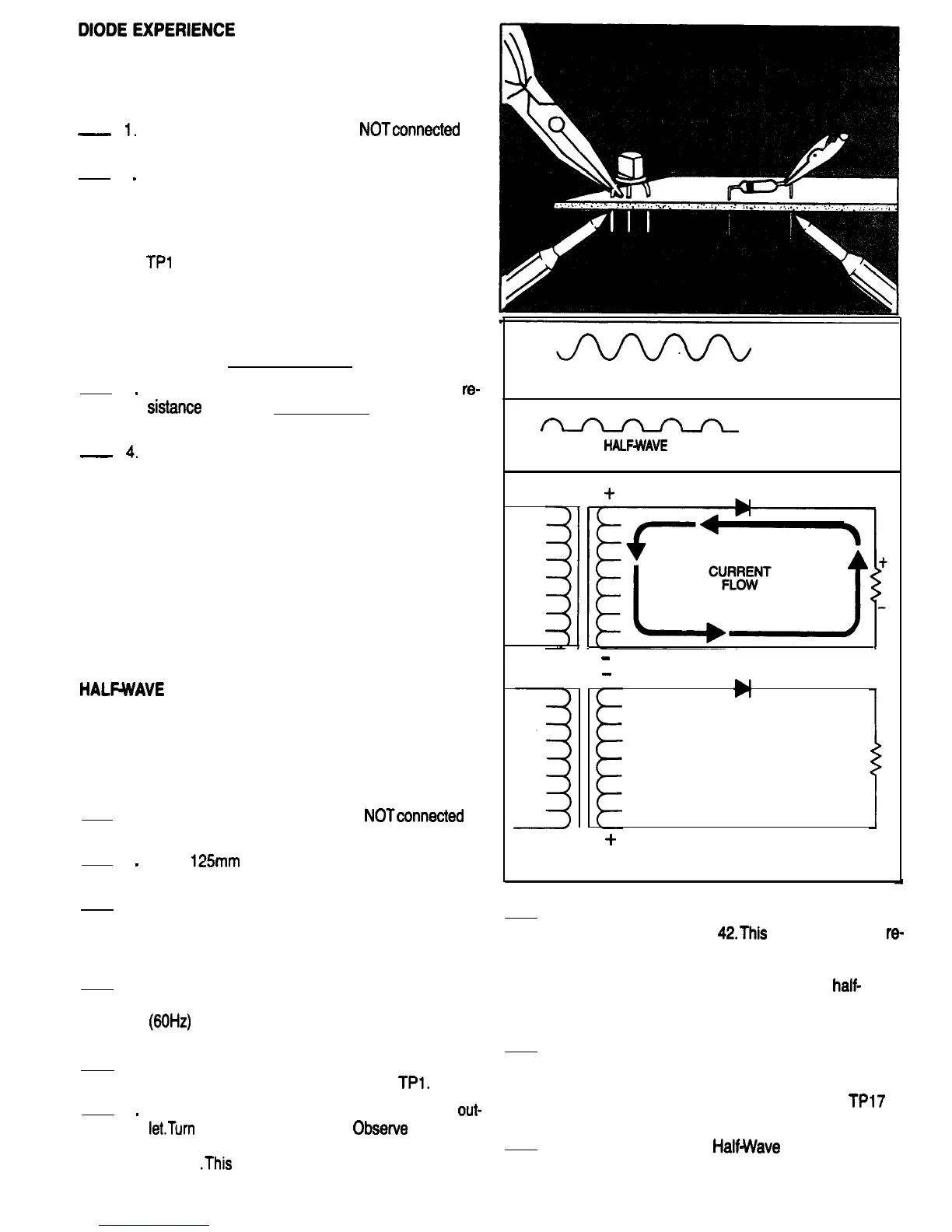
Fig. 41
.This
is ac voltage which is present at the
secondary winding of the transformer.
TRANSFORMER
SECONDARY
AC VOLTAGE
FIG. 41
a
CATHODE OF Dl
HALFWAVE
RECTIFICATION
FIG. 42
+
l
-
-
NO
CURRENT
FLOW
+
HALF WAVE RECTIFIER CIRCUIT
L
FIG. 43
7. Move the scope probe to TP17. The waveform
should look like Fig.
42.This
waveform is the
re-
sult of diode Dl rectifying the ac voltage. Dl clips
off the negative half of the waveform, leaving
only the positive half. This is called
half-
wave
rectification. Current flow in a half-wave rectifier
circuit is illustrated in Fig. 43.
8. Turn the 808 Power switch Off and disconnect
the power plug from the outlet. Disconnect the
scope common lead and input Probe. Leave the
red wire that is soldered to TP8 and
TPl7
in
place.
9. This completes the
HalfWave
Rectifier Experi-
ence. Have your instructor initial your Progress
Guide.
24

 Loading...