FULLWAVE
CENTER-TAPPED RECTIFIERS
DISCUSSION
A
FuMVave
center-tapped rectifier circuit requires a trans-
former with a secondary winding which has a tap halfway
between both ends of the winding (a center-tap). secondary
number 2 of the 808 Power Supply transformer is a
center-
tapped winding. You have already used one half of this
winding in the
HalfWave
Rectifier section.
FULLWAVE
CENTER-TAPPED
RECTIFIER EXPERIENCE
Pupose:
To observe the voltage waveform produced by a
FukWave
Center-Typed
Rectifier circuit.
Equipment: Oscilloscope
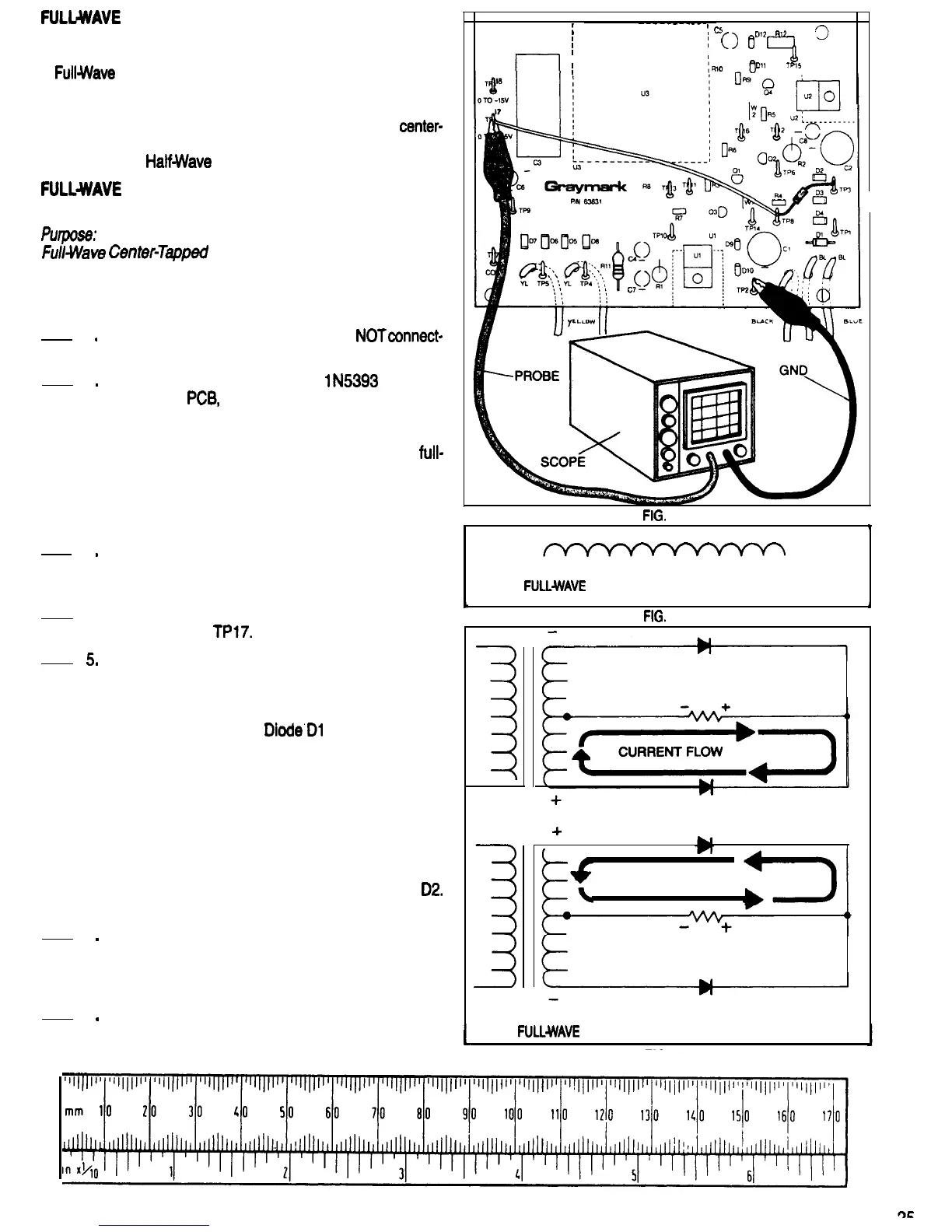
Refer to Fig. 44 for the following steps.
1
.
2
.
Be sure that the 808 power plug is
NOTconnect-
ed to a power outlet.
3
.
4
l
5
.
Solder the cathode lead of a
lN5393
diode to
TP8 of the
PCB,
and the anode lead toTP3. Do
not cut the diode leads, or remove the red wire
soldered to TP8. This is a temporary installation
of D2. This diode will be removed after the
full-
wave filter test and installed later in its permanent
location. Since the long leads isolate the heat of
soldering from the diode itself, it is not necessary
to use a heat sink.
Turn the scope ON and let it warm up. Adjust it
to display a 60 Volt (peak to peak) 60 Hz signal.
Set the vertical input (Y) coupling to DC.
Connect the scope ground lead toTP2, and the
’
I
FIG.
45
input probe to
TPl7.
Connect the 808 Power Supply plug to a power
outlet. Turn the power switch ON. The waveform
displayed on the scope should look like Fig. 45.
Both halves of the ac cycle are now being recti-
fied. Refer to Fig. 46.
Diode’Dl
rectifies the cur-
rent from one half of the secondary winding, and
diode D2 rectifies the current from the other half
of the winding. Since the diode cathodes are
connected together, both their waveforms are
joined together to produce a composite wave-
form. This composite waveform is composed of
two sets of positive voltage half cycles. One set
is from Dl ,and the other set, which is 180 de-
grees out of phase with the first set, is from
D2.
This is called full-wave rectification.
6
.
Turn the 808 Power switch OFF and disconnect
the power plug from the outlet. Disconnect the
scope common lead and input probe. Leave di-
ode D2 and the red wire in place.
7
.
This completes the Full-Wave Center-Tapped
0
;
-----------
;
cs
I
DI?
f772
I
i
0
0
I
I--
l
I
?!!I
I
Cl1
TPl5
I
r---------
FIG.
44
*
FULLWAVE
RECTIFICATION, POSITIVE OUTPUT
NO CURRENT FLOW
+
CURRENT FLOW
NO CURRENT FLOW
FULLWAVE
CENTER-TAPPED RECTIFIER CIRCUIT
Rectifier Test. Have your instructor initial your
Progress Guide.
L
FIG. 46

 Loading...