CENTER-TAPPED
FULLWAVE
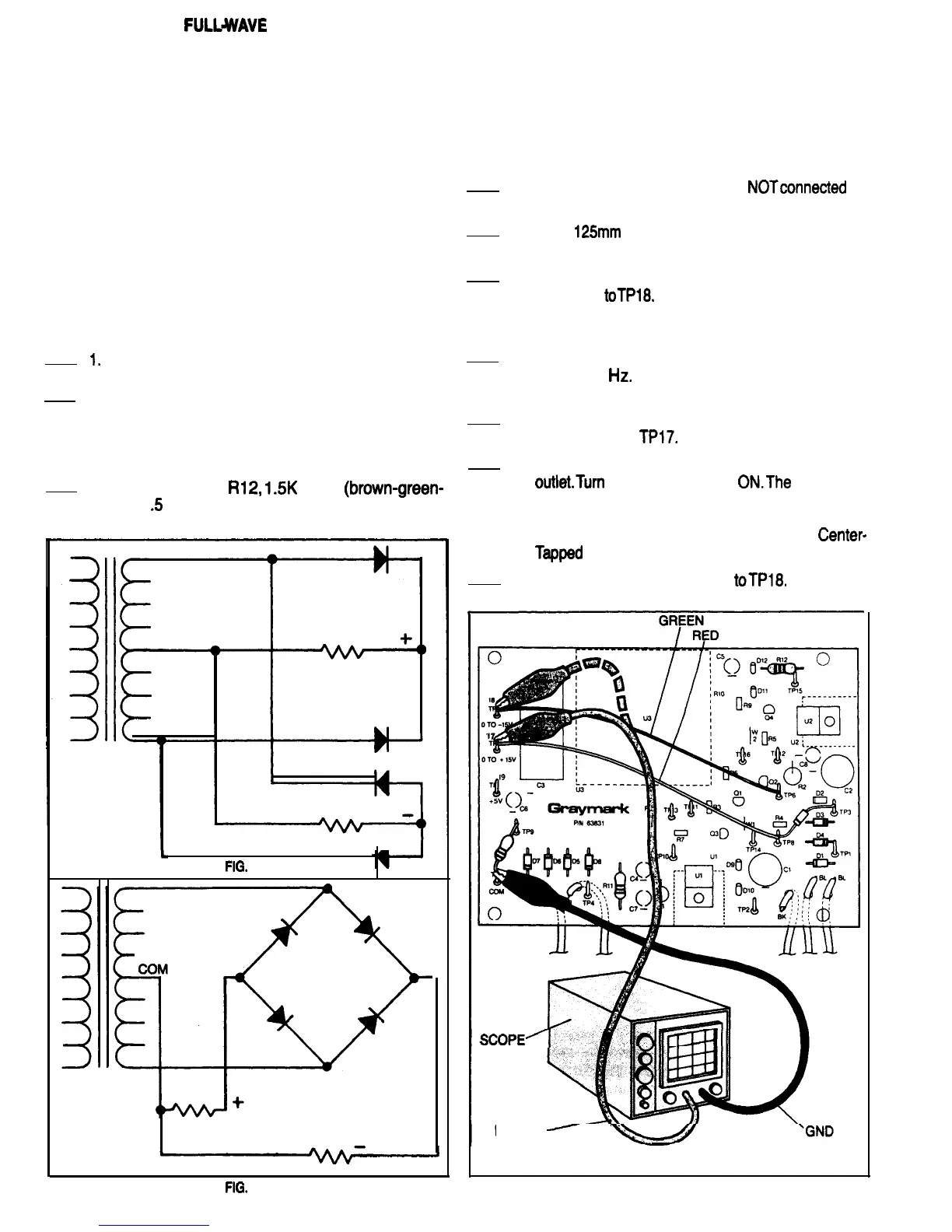
BRIDGE RECTIFIERS
DISCUSSION
As mentioned before, the center-tapped full-wave bridge
rectifier circuit combines features of both the center-tapped
full-wave and the full-wave bridge rectifier circuits. It has
two equal voltage outputs of opposing polarity as referred
to the transformer secondary center tap. Figures 49A and
49B are schematics of the same rectifier circuit. Figure 49A
is drawn to illustrate that a center-tapped full-wave bridge
rectifier is made by connecting two center-tapped full-wave
rectifiers to a common center tapped transformer second-
ary winding. Figure 49B shows the same circuit, drawn dif-
ferently to illustrate that a center-tapped full-wave bridge
rectifier can also be considered to be a full-wave bridge rec-
tifier with a added center-tap on the transformer winding.
CONSTRUCTION
Refer to Fig. 50 tor the following steps.
I.
Be sure the 808 power plug is not connected to
a power outlet.
2.
Mount diodes D3 and D4 to the PCB. Be sure the
banded ends of the diodes are oriented the
same as the diode outlines that are silk screened
on the PCB. Using a heat sink, solder each diode
lead to the PCB, and cut off any excess lead
3. Mount resistor Rl2,
1.5K
Ohm
(brown-green-
red),
.5
Watt, on the PCB. Solder the resistor
leads to the PCB and cut off any excess length.
1
FIG.
49A
CENTER-TAPPED FULL-WAVE BRIDGE RECTIFIER
EXPERIENCE
Purpose: To observe the voltages and waveforms pro-
duced by a Full-Wave Center-Tapped Bridge Rectifier
Circuit
Equipment: Oscilloscope
Refer to Fig. 50 for the following steps.
1.
Be sure the 808 power plug is
NOTconnected
to
a power outlet.
2.
Cut a
125mm
length of green 22 gauge wire, and
strip 6mm of insulation from each end.
3.
Solder one end of the green wire toTP6, and the
other end
toTPl8.
Because these are temporary
connections for testing purposes, it is not neces-
sary to make mechanical connections.
4. Adjust the scope to display a 60 Volt (peak to
peak) 60 Hz signal. Set the vertical (Y) input
coupling to DC.
5. Connect the scope ground lead to TP7 and the
input probe to
TPl7.
6. Connect the 808 Power Supply plug to a power
outlet.Turn
the Power Switch
ON.The
waveform
displayed on the scope should look like Fig. 45.
This is the same waveform being produced by
the same circuitry as in the Full-Wave
Center-
Typed
Rectifier Test that you did earlier.
7. Move the scope input probe
toTPl8,
The wave-
form displayed on the scope now should look like
SCOPE1
PROBE
-
\
FIG.
49B
FIG. 50
27

 Loading...