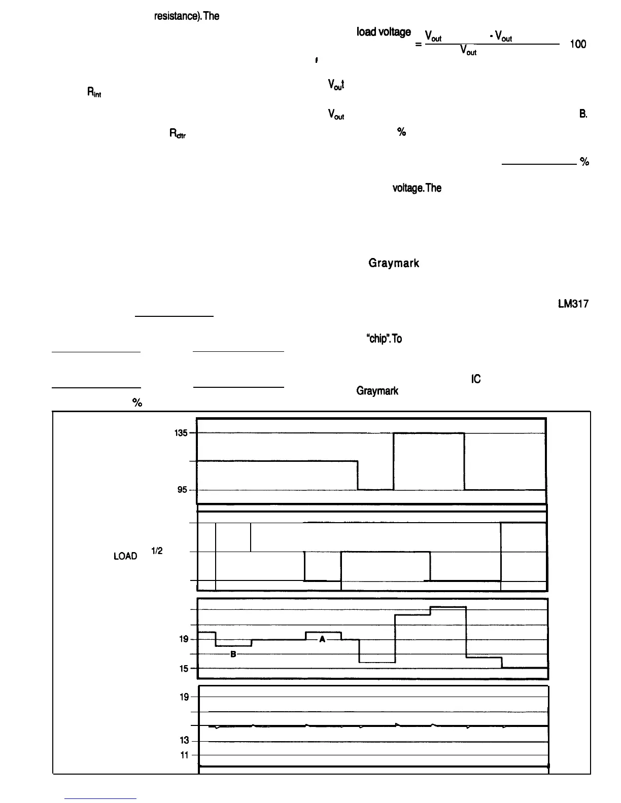
and full load (50 Ohms
resistance).The
changing condition
following formula:
of these loads is shown by the second graph.
%
toad
“*Itage
Figure 78 is the equivalent circuits of the unregulated and
regulation
=
Vout
(no load)
-
Vout
(full load) x
1
o.
the regulated power supplies. The boxes labeled INPUT
I
Vout
(full load)
POWER CONDITIONING represent the input circuitry,
At the nominal line input voltage of 115 Volts.
power transformer, rectifiers and input filters. The resistors
labeled
Ri”t
represent all the losses and resistances in the
VOJ
(no load) occurs at the point on the Unregulated Power
components mentioned above.
Supply Output graph that is marked with the letter A.
Vout
(full load) occurs at the point marked with the letter
B.
In the equivalent circuit of the regulated power supply, the
variable resistor labeled
R&r
represents the Darlington
transistor in the voltage regulator that controls the current
that flows through the regulator to the load resistors. The
load resistors are shown with push-button switches,
ganged together between the two loads. With this setup,
the load conditions shown in the second graph could be
duplicated by manipulating the switches.
Calculate the
%
load voltage regulation for this power
supply and write your answer in the space provided.
OO
/
The bottom graph in Fig. 77, shows the regulated power
supply output
voltageThe
little “glitches’ appearing on this
graph indicate that the voltage regulator cannot instantly
compensate for input voltage and load changes. More
about that later.
How voltage regulators actually work will be discussed in
more detail a little later. Right now we just want to see the
differences in the output voltages of unregulated and
regulated power supplies with varying line input voltages
and loads.
The third graph from the top shows the output voltage of the
unregulated power supply. What is the worst case voltage
variation in Volts?
Most real life regulators won’t provide the zero percent
regulation shown on the graph, but the voltage regulators
in your
Graymark
808 Power Supply will provide
considerably better than 1% combined line and load
regulation.
Figure 79 shows the schematic diagram of the
LM317
voltage regulator. Transistors, resistors, Zener diodes and
Under what conditions is the output voltage the highest?
capacitors are formed in a small piece of silicon, often
called a
“chip”.To
help understand how a voltage regulator
Input line.
Load.
functions, we will be using a functional schematic, which
Under what conditions is the output voltage the lowest?
is shown in Fig. 80.
Input line.
Load.
The operation of all three of the
IC
voltage regulators used
in the
Graymark
808 Power Supply is based on the same
To calculate the
%
load voltage regulation, use the
general principles. The following discussion applies to the
INPUT
LINE 115
VOLTAGE
FULL LOAD
(50 OHMS)
112
LOAD
‘OAD
(100 OHMS)
NO LOAD
23
21
UNREGULATED
POWER SUPPLY
lg
OUTPUT (VOLTS) 17
17
REGULATED
POWER SUPPLY 15
OUTPUT (VOLTS)
l3
FIG. 77
42
 Loading...