LM309,
the
LM317
and the LM337. The LM337 is a
negative
regulator,that
is, its input and output voltages are
negative in respect to ground. This results in different
polarities inside the
IC,
but it operates according to the
same principles as the
LM309
and
LM317.
UNREGUUKTED
POWER SUPPLY
REGUIATED
POWER SUPPLY
FIG.
78
REPRINED
WITH
PERMISSION OF NATIONAL SEMICONDUCTOR
COF?PORAT/ON
FIG.
79
INPUT
,
DARLINGTON
TRANSISTOR
------1
0
OUTPUT
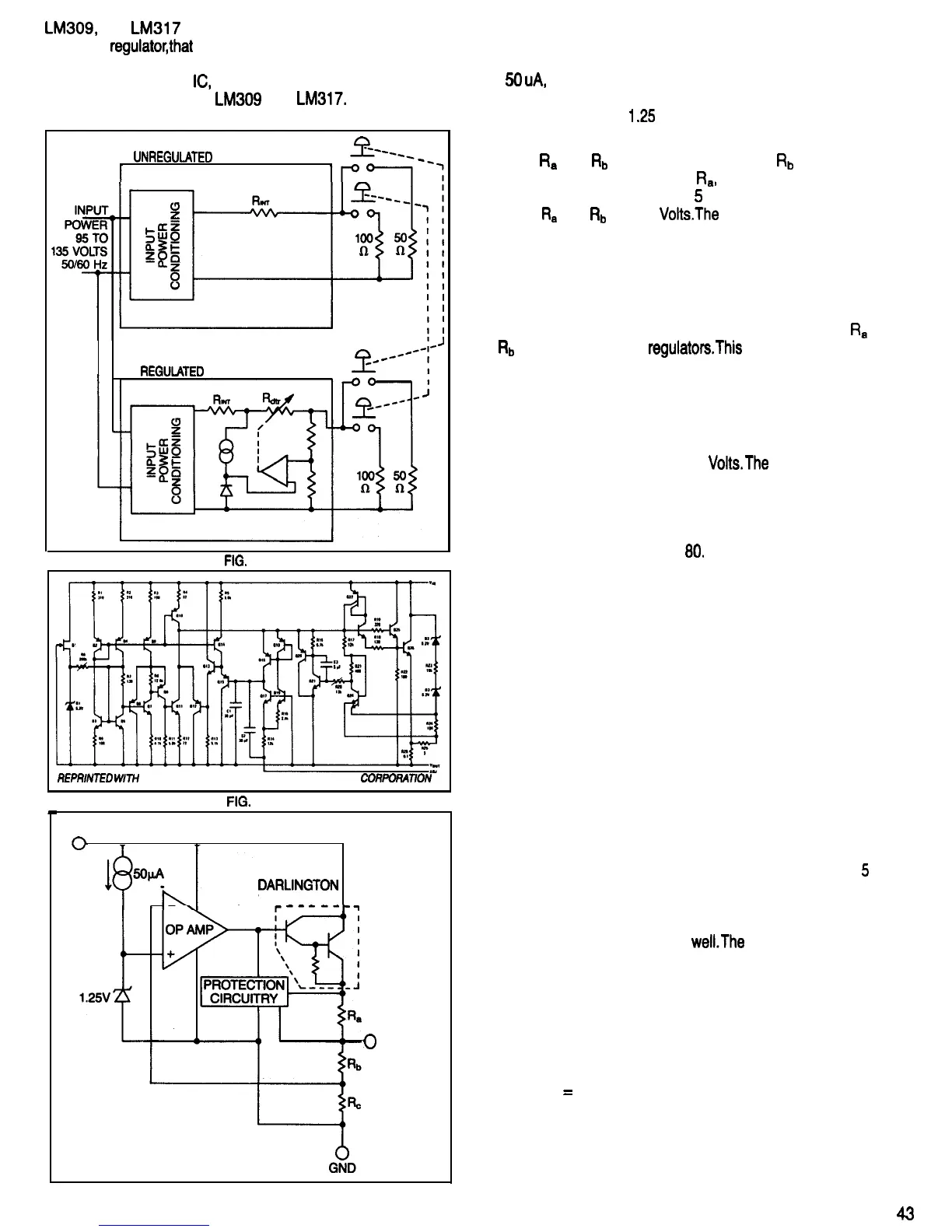
The two overlapping circles and the arrow in the upper left
hand corner of the schematic form the symbol for a current
source. A current source will pass a constant current, in this
case
50
uA,
despite variations of the voltage appearing
across its terminals. This current source provides a
constant current for the
I
.25
Volt Zener diode that supplies
the reference voltage for the regulator.
Resistors
R*
and
Rb
form a voltage divider.
Rb
has three
times the resistance in Ohms of
Ra,
so when the voltage
at the regulator output terminal is
5
Volts, the voltage at the
junction of
R*
and
Rb
is 1.25
Volts.The
operational amplifier
(op amp) compares this portion of output voltage of the
regulator to the 1.25 Volt reference voltage. As long as the
two input terminals of the op amp are at the same voltage,
there is very little current flowing either into or out of the op
amp output terminal.
The adjustable voltage regulators are a little different.
Ra
and
Rb
are external to the
regulatorsThis
will be discussed
later in the EXTERNAL CONTROL AND PROTECTION
CIRCUITRY section.
If we increase the voltage regulator load by connecting a
resistor between the regulator output and ground, the
additional current flowing through the regulator will cause
the output voltage to drop below 5
Volts.The
voltage at the
op amp input terminal marked with the minus sign drops
as well. The op amp responds to this input change by
moving its output in a positive direction, causing an
increase in the base current of the Darlington transistor
shown at the right side of Fig.
80.
The Darlington transistor is named after the person who
invented this particular way of connecting two transistors
and a resistor together to form the equivalent of one
transistor. A Darlington transistor requires very little base
input current to control the collector output current, and can
respond to rapid changes of the base current.
A transistor can be thought of as a valve that controls the
flow of electrons, that is, the current in a circuit. The “valve
handle” of the transistor is its base. The amount of current
flowing through the transistor from emitter to collector is
controlled by a much smaller current flowing from the
emitter to the base.
Another way of looking at a transistor is to consider it as a
variable resistor, where an increase in the base current
causes a decrease in the resistance.
At this point, the output of the voltage regulator is below
5
Volts because an additional load resistor was connected
between its output terminal and ground. This lowered
output voltage caused the voltage at the inverting input of
the op amp to become lower as
well.The
op amp responds
to this input voltage change by by moving its output in a
positive direction, increasing the base current of the
Darlington transistor.
The resulting decrease of resistance between the
Darlington transistor’s emitter and collector causes an
increase in the current flowing through the voltage
regulator and the load resistors. In accordance with Ohm’s
law, (voltage
=
current x resistance), the output voltage of
the voltage regulator heads back up to 5 Volts.
Figure 81 shows the effects of connecting a load resistor
to the output of a voltage regulator. The conditions shown
in the right portion of the figure occur after the load resistor
FIG. 80
43
 Loading...