5.
Position the breadboard on the cabinet top, so
the printing on the breadboard is readable. While
holding the breadboard in place, turn the cabinet
top over.
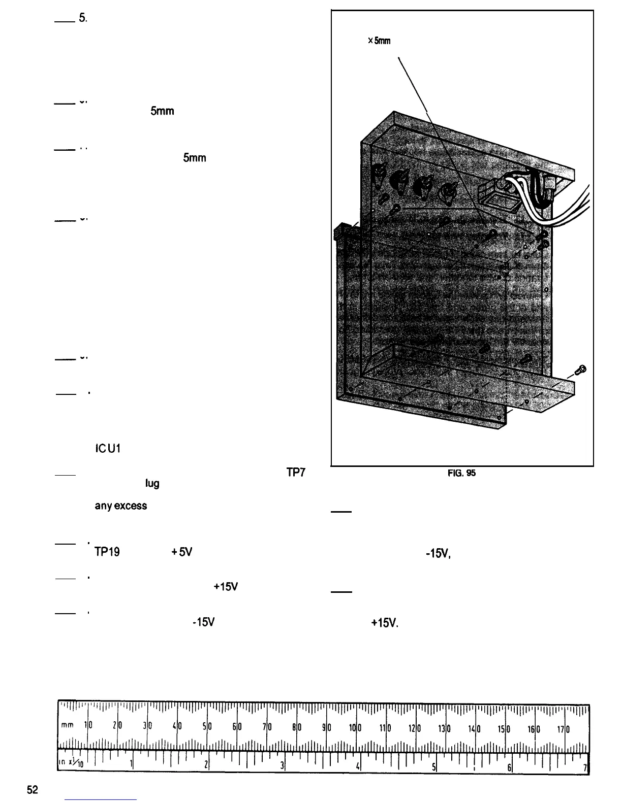
Refer to Fig. 95 for the following steps.
6
-0
7
-’
Refer to
8
-*
9
-0
10
.
11.
12
.
13
.
14
.
Attach the breadboard to the cabinet top using
eight 2.6 x
5mm
self-tapping screws. Do not
over tighten the screws.
Attach the breadboard bus strip to the cabinet
top using two 2.6 x
5mm
self-tapping screws. Do
not over tighten the screws.
Fig. 96 for the following steps.’
Position the transformer so the side with the two
white wires is next to the cabinet side. Mount the
transformer to the cabinet bottom using two 3 x
8mm machine screws, two 3mm flat washers,
two 3mm lockwashers, and two 3mm nuts. Place
the solder lug which is attached to the green
wire from the PCB between the transformer and
the cabinet bottom as shown in Fig. 96. This
wire provides an electrical connection between
Common (ground) on the PCB and the metal
cabinet.
Unscrew and remove the four screws which are
holding the standoffs at each corner of the PCB.
Using the screws, standoffs and nuts removed in
the previous step, mount the PCB to the cabinet
bottom. Place four 3mm lockwashers between
the top of the PCB and the two 3mm nuts and
the two long standoffs. Position the PCB so that
IC
Ul is next to the transformer.
Connect and solder the black wire from
TP7
to
the solder
lug
on the black binding post which
was installed on the cabinet top earlier, Cut off
any
excess
wire that sticks out beyond the
solder lug.
Repeat Step 11, connecting the red wire from
TPl9
to the red
+
5V binding post.
2.6
x
5mm
SELF-TAPPING SCREWS
(10 PLACES)
FIG.
95
15. Place a 7mm lo&washer over the threaded
bushing of the potentiometer which is connected
to the PCB with two green wires. Mount the
potentiometer in the hole in the cabinet top
marked 0 to
AS/,
using a 7mm flat washer and
hex nut.
Repeat Step 11, connecting the orange wire
from TP17 to the red 0 to
+15V
binding post.
16. Repeat the previous step using the
Repeat Step 11, connecting the gray wire from
potentiometer connected to the PCB with two
TP18 to the red 0 to -15V binding post.
red wires, mounting it in the hole marked 0 to
+15v.

 Loading...