FINAL PCB ASSEMBLY
1. Be sure that the 808 power plug is NOT
connected to a power outlet. Refer to Fig. 92 for
the following steps.
2.
Locate the four
15Omm
lengths of 18 gauge wire.
strip 6mm of insulation from each end of each of
the four wires. Twist the fine strands of exposed
wire on each of the ends together and tin them.
Form one of the tinned ends of each of the wires
into a hook shape with a long nose pliers.
Connect and solder these hooked wire ends to
the following test points on the PCB.
-
A. The black wire to TP 7.
-
B.
The red wire to TP 19.
-
C. The orange wire to TP 17.
_
D,
The gray wire to TP 18.
3.
Cut a 1
OOmm
piece of green 22 gauge wire. Strip
6mm of insulation from each
end.Twist?he
small
strands of wire together, and tin both ends.
4.
Connect and solder the
3.5mm
solder lug to one
end of the green wire that you prepared in the
previous step. Connect and solder the other end
of this wire to the PCB. Use the unmarked hole
near TP 7. Cut off any excess wire.
5. This completes the FINAL PCB ASSEMBLY.
Have your instructor initial your progress guide.
CABINET ASSEMBLY
CAUTION!
Be sure that the AC Cord is NOT plugged
into an electrical outlet during this Cabinet
Assem
biy
Section.
1.
Mount two rubber feet to one end of the cabinet
bottom, using two 3 x 8mm self-tapping screws.
Refer to Fig. 94.
2.
Repeat the previous step for the other end of the
cabinet bottom.
3. Remove the protective plastic from the
breadboard.
4. Place the cabinet top face up on your work
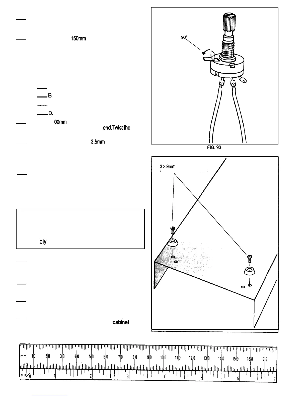
BEND
TAB
90’
\
FIG.
93
3x9mm
SELF-TAPPING SCREWS
-.-
-
FIG. 94
surface, so the printing on the
cabirnet
top is
readable.

 Loading...