BLACK 18 GAUGE
GREEN 2
5.
Disconnect both meter leads and reconnect the
be used.
6
.
positive meter lead to TP 11 and the negative
lead
toTP
14.The
meter will now read the voltage
between the emitter and base of
Q3.What
is the
meter reading now?
(The clip lead should still be connected
toTP
7
and TP
17.)
Remove the clip lead fromTP7 and TP 17. What
is the voltage across the base
/
emitter junction
of
Q3
now?
VOLTAGE CONTROL OPERATIONALTEST
Pupose:
To determine that the external voltage control
circuitry is working properly
In step
5
the voltage across the base
/
emitter
junction was more than 0.5 Volts, and current
was flowing from the collector to the emitter. In
this step the voltage from the base to the emitter
of
Q3
was very low, so there was almost no
current flowing from the collector to the emitter.
7. Turn OFF the 808 power switch and disconnect
the power plug from the power outlet. Remove
the test clip and meter leads. Remove the two 3.9
kOhm
test resistors from
TPI
3, TP14,
TPI
5 and
TP16.
6. Repeat step 5, this time using the two red wires
and the second potentiometer.
7.
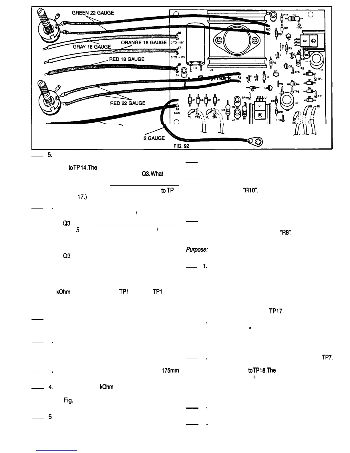
Insert the free ends of the green wires in the PCB
holes that are nearest to the silk screened
designation
“RlO”.
Solder the wires to the PCB
and cut off any excess length. It doesn’t matter
which of the two wires goes into which of the two
holes.
8.
Repeat step 7, this time using the free ends of the
two red wires and the two holes on the PCB
closest to the designation
“R8”.
1
.
CONSTRUCTION
-
1.
2
.
3
.
-
4.
5.
Be sure that the 808 power plug is not connected
to a power outlet. Refer to Fig. 92 for the following
--
2
.
steps.
Cut two 200mm pieces of green 22 gauge wire
and strip 6mm of insulation from all four ends.
Twist the exposed strands of fine wire together
on each end and tin them.
3
.
Repeat step 2, cutting and preparing two
175mm
pieces of red 22 gauge wire.
Locate the two 5
kOhm
potentiometers. Bend the
small metal tab on each potentiometer as shown
in
Fig.
93 so that it won’t interfere when the
potentiometer is mounted on the cabinet top.
_
4
.
Connect and solder the two green wires
prepared in step 2 to one of the potentiometers
_
5
.
as shown in Fig. 93. It is important that the
correct solder terminals of the variable resistors
During this test be careful not to let the terminals
of the potentiometers touch the PCB or any of the
components. Rotate the control shafts of both
potentiometers to the full counter clockwise
position. Adjust the range selector of your VOM
or DMM to measure up to 20 Volts DC. Connect
the negative meter lead to TP7. Connect the
positive meter lead to
TPl7.
Power up the 808. The voltmeter should read
between 0 and
-
0.3 Volts. Rotate the Shaft of the
potentiometer connected to the red wires to the
full clockwise position.The voltmeter should now
read between 15.5 and 20 Volts.
Remove the voltmeter leads fromTP17 and
TP7.
Reconnect the positive meter lead toTP7 and the
Negative lead
toTPl8.The
voltmeter should read
between 0 and
+
0.3 Volts. Rotate the shaft of
the potentiometer connected to the green wires
to the full clockwise position. The meter should
now read between 15.5 and 20 Volts.
Turn OFF the 808 power switch and disconnect
the power plug from the power outlet.
This completes the VOLTAGE CONTROL
OPERATIONAL TEST Have your instructor
initial your progress guide.
50

 Loading...