3
.
4
.
5
.
6
.
FIG.
90
pieces of wire for the next step.
Bend the piece of wire saved from the previous
step into a U shape and use it for jumper wire
Wl
.
Insert this wire from the component side of the
PCB.
Solder it to the PCB and cut off any excess
length.
Locate the two transistors that are marked 9015.
There may be other numbers or letter as well,
such as
CQOl5A
QC, but the numbers 9015 will
appear within the sequence of
charactersThese
are the PNP transistors and are used for
Ql
and
C4.
Spread the leads to form a triangle, and
mount these transistors on the
PCB,
making
sure that they are oriented the same as the D
shaped transistor outlines that are silk screened
on the PCB. Solder the leads to the PCB, using
a heat sink as shown in Fig. 40 on each lead as
you solder it.
Repeat Step 4, using the transistors marked
9014. These are the NPN transistors and are
used for
Q2
and
Q3.
This completes the construction of the external
protection circuitry. Have your instructor initial
your progress guide.
1
.
2
.
3
.
4
.
5
.
Connect the 808 power plug to a power outlet.
Turn the 808 power switch ON, wait 1 second
and turn it OFF touch the components that were
installed in the construction steps just
completed. If any of these components are
warm, there is something wrong. Check the PCB
and components carefully, and consult with your
instructor if necessary.
Repeat step 2, leaving the power ON for 5
seconds this time.
.
Repeat step 2 again, leaving the power ON for
15 seconds this time.
If none of the components heated up in the
previous steps, power up the 808 again.
Measure the DC voltage between test pointsTP7
and TP17. TP17 should be positive,and the
voltage should be between 12.7 and 15.8 Volts.
Then measure the DC voltage betweenTP7 and
TPl8.
TP18 should be negative and the voltage
should again be between 12.7 and 15.8 Volts. If
these voltages are not within these ranges,
check transistors
Ql
through
CJ4
for proper
location and orientation. Consult with your
instructor if necessary.
OVERCURRENT
PROTECTION EXPERIENCE
Purpose: To demonstrate the operation of the external
overcurrent
protection circuitry used in the
Graymark
808
Power Supply
Equipment:
VOM
or
DMM
Clip Lead
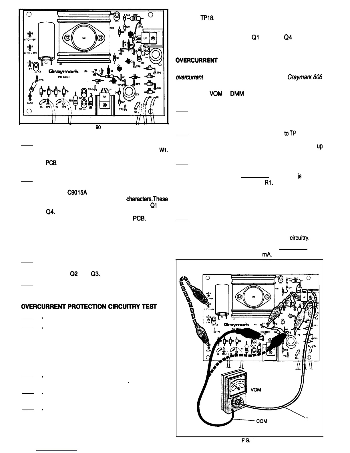
1.
Be sure that the 808 power plug is not connected
to a power outlet. Refer to Fig. 91 for the following
steps.
2. Connect the positive meter lead
toTP
8 and the
negative meter lead to TP 10. Set the meter
range selector switch to a range that will read
up
to 1 Volt DC.
3. Connect the 808 power plug to an electrical
outlet and turn the power switch ON. What is the
meter reading?
The meter
is
reading
the voltage drop across
Rl,
the 1 Ohm current
sensing resistor. What is the current flowing
through the resistor? Use the short cut way of
calculating the current value that was discussed
earlier in this manual.
4. Connect the clip lead to TP7 and TP17. This
provides a very low resistance load for the
positive variable power supply, and will activate
its external overcurrent protection
circuitv.
How
much current is flowing now?
It should be about 500
mA.
FIG.
91
4

 Loading...