ABCOE
1
l
*eme
2
l l l l l
2
l . l l l
1
l l l l l
s
l l l l l
b
l l l l l
7
l l l l l
8
l
e
l l l
9
l l l l l
IO
l l l l l
11
l l l l l
I?
l l l l l
13
l l l l l
14
l l l l l
15
l l l
0
l
16
l l l l l
17
l oeee
18
l l l l l
19
l l l l l
20 l l l l l
21
l l l l l
22
l eeee
13
l eeee
t4
l l l l
0
25
l eeee
2b
l l l l l
2r l eeee
0
l l l l
T
FGHI
J
l
****~
l eeee2
l eeee
3
l eeee
4
l eeee
5
l eeee b
l eeee
7
l eeee
6
l eeee 9
l l l l l 10
l l l l l
11
l l l l l 12
l l l l l
13
l l l l l 14
l l l l l 15
l l l l l
19
l l l l l
17
l l l l l
16
l l l l l 19
l l l l
0
20
l
0
l l
0
21
l l l
a
l 22
0
l l l
0
23
l l
0
l l 24
a
l
0
l
0
25
l l l l l 2b
l l l l l 27
l l l l l
?a
1
l l l l l
2
l l l l l
3
l l l l l
4
l l l l l
5
deeee
6
l l l l l
?
l l l l
0
8
l eeee
9
l l l l l
10 l l l l l
11
l l l l l
12
l l l l l
13
l eeee
14 l eeee
15 l eeee
lb l l l l l
l? l oeee
18
l l l l l
19 l l
0
l l
20
0
l l l
0
I1
l eeoo
I2
l eeee
13
0
0
l l
0
I4 l *moo
15
l
a
l l
0
16
l l l l l
17
ae*ee
ta
+
*
-
FIG. 102
l l l
0
l
14
l l l l l 15
l l l l l
19
l eoe*l7
l l l l l
19
l l l l l 19
l l l l l 20
l l l l l
21
l l l
0
0
22
0 l 0 l
0
23
l
a
a
l l 24
0 l l l
0 25
0 l l
0
l 29
l l l l l 27
a---m2a
A0COE
1
*em**
2
l eee*
3
l l l l l
4
l l l l l
5
l l l l l
b
l l l l l
7
l
0
l l l
I
0 l l l l
9
l l l l l
13
l eeee
14
l l l l
0
15
l eeee
20
0
l l l
0
21
l eeee
12
l l l l
0
i3
l l l l l
14
l
0
l l l
25
a
l l l
0
29
l l l
0
l
27
l l a l l
3n
0
9
l
9
l
FGH
I
J
me***
1
l eeee
2
l eeee 3
l e*e* 4
l eeee 5
l eeee
6
l eeee
7
l eo*e
9
l eeee 9
l l l
0
l 10
0
l l l l
11
l ee*e 12
l l l l l 13
l l l l
a
14
l l l l l 15
l l l l l lb
l
a
l l l I?
0
l l l
0
10
l l
a
l l 19
l
0
l l 0
2a
l
0
0
l l 21
l l
0
0
l 22
l l l l
a
23
a
l l l
w
24
l l l l
8
25
0 l l l l 26
0
l l
0
0 27
l l l
0
l 28
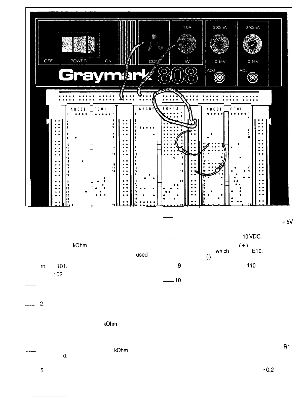
the interconnections in both the bus strip and the
component sections.
Sample Circuit
Equipment: VOM or DMM
Two 3.9
kOhm
Resistors
To demonstrate how the Breadboard can be
used#
to
construct circuits, you can build the voltage divider circuit
shown
m
Fig.
101.
Refer to Fig.
102
for the following steps.
-~
1.
-
2.
3.
~-
4.
5.
Connect one end of a wire to the COM terminal.
Insert the other end of the wire into the hole in the
upper bus strip as shown.
Insert one end of a wire into the hole in the upper
bus strip as shown. Insert the other end into the
hole in the vertical bus strip as shown.
Insert one end of a 3.9
kOhm
resistor into the
hole in the vertical bus strip as shown. Insert the
other end in hole Al 0 in the center component
section.
Insert one end of another 3.9
kOhm
resistor into
hole El
0.
Insert the other end into the hole in the
vertical bus strip as shown.
Insert one end of a wire into the hole in the
vertical bus strip as shown. Insert the other end
into the hole in the upper bus strip as shown.
6. Insert one end of a wire into the upper bus strip
as shown. Connect the other end to the
+5V
terminal.
7. Adjust the meter to read
IO
VDC.
8. Connect the positive
(
+)
meter lead to the
resistor lead
ihich
is in hole
EIO.
Connect the
negative
(-)
meter lead to the COM terminal.
Plug the Model 808 into a
I
IO
VAC outlet and
turn the Power ON.
Read the meter. It should read approximately 2.5
VDC, showing that the voltage divider circuit is
performing as expected. Since the circuit is
operating as expected, you know that the circuit
which you built on the Breadboard is connected
in accordance with the schematic in Fig. 101.
9
10
11. Turn the Power OFF and unplug the Model 808.
12. Remove the meter and all wires and resistors
from the Breadboard.
NOTE: Due to the nature of the design, when the Positive
and Negative Variable Voltage control pots (R8 and
Rl
0)
are set to the full counter-clockwise position (for minimum
output), the output voltage level can go past zero and
produce an output in the opposite polarity. Levels up-
wards of one to two hundred millivolts (0.1
-
0.2
Volts) of
reversed polarity are possible, and can adversely affect
some semiconductor devices, Make sure that you have
58
 Loading...