the two Variable Voltage Outputs set to the desired level
before connecting them to the breadboarded circuit, and
do not randomly adjust the control pots during operating.
If your
Graymark
project does not operate correctly, the
following steps will help you to isolate the
problem.There
are three basic steps to follow when servicing any
electronic device.
I.
Isolate the defective section.
Ii.
Isolate the defective component or connection.
Ill. Repair or replace the defective component or
connection.
Check off each step as you proceed.
1. Check ALL solder connections. Poorly soldered
for their part numbers. Each
IC
must be in the
connections should be reheated to form good
correct location.
joints. Refer to the HOW TO SOLDER section for
examples of good and poor solder connections.
4. If the above procedures fail to locate the
problem, performing the experiences located
2. Check the placement of ALL components. Make
sure that the
(-)
leads of
electrolytic
capacitors
are going into the PCB holes marked
(0).
Be
certain that you have installed the proper
capacitors in the right locations. It is easy to get
confused by the numbers on capacitors. Check
that all resistors have been installed in their
proper locations. Resistor values can be
determined by the RESISTOR COLOR CODE
section.
throughout the manual will be helpful in locating
the problem, especially if you built the Power
Supply using Mode
Il.
These experiences
demonstrate how the various sections of your
Power Supply operate. If you find results that
differ greatly from those described, you will know
where to look for trouble in your Power Supply.
Be sure that each
IC
has been installed in the
proper location. Ul and U2 look similar, except
3
.
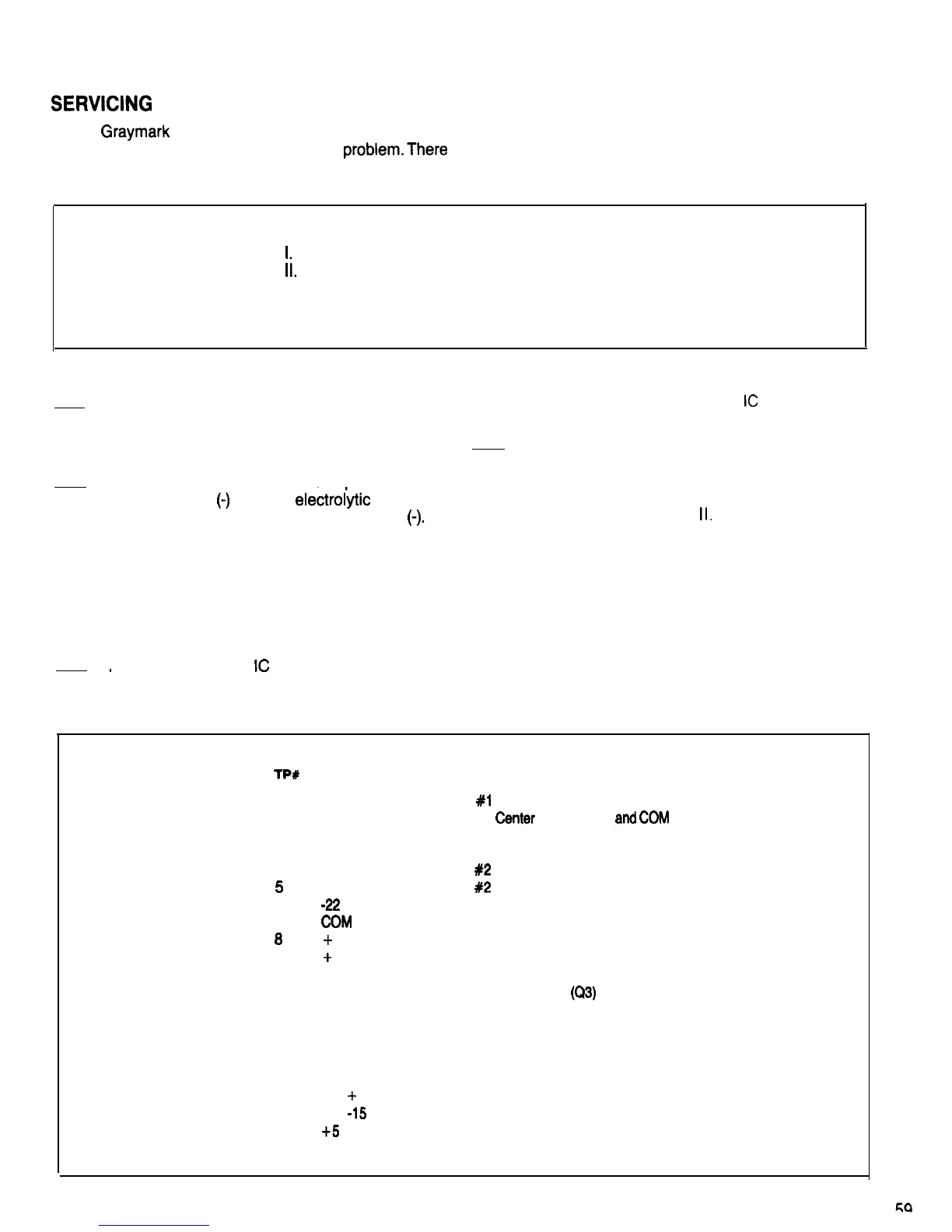
TEST POINT DESCRIPTIONS
lP#
DESCRIPTION
1
2
Transformer Secondary
#l
Start (Blue)
Transformer Secondary #1
Center
Tap (Black)
and
(XXI!
(Ground)
3
4
5
6
7
0
9
10
11
12
13
14
15
16
17
18
19
Transformer Secondary #1 Finish (Blue)
Transformer Secondary
#2
Start (Yellow)
Transformer Secondary
#2
Finish (Yellow)
-22
Volts, Unregulated
COM
(Ground)
+
22 Volts, Unregulated
+
11 Volts, Unregulated
Positive Regulator Input Terminal
Overcurrent Protection Transistor Base
(Q3)
Negative Voltage Regulator Input Terminal
Positive Voltage Regulator Adjust Terminal
Minus 1.4 Volt Voltage Control Bias
Negative Voltage Regulator Input Terminal
Positive 1.4 Volt Voltage Control Bias
0 to
+
15 Volt Output, Regulated
0 to
-15
Volt Output, Regulated
+5
Volt Output, Regulated

 Loading...