ENGLISH
Installation and General Maintenance Manual - MONOBLOCK FILTER 5
• Connect the other end of the suction hose to the skimmer tightening firmly with a clamp. Repeat the same procedure with
the return nozzle terminal and connect the discharge hose.
• Following installation, the first cycle of filter backwash should be performed. In order to do so, follow the instructions in section 5.3.
• It is important to check that the suction ports are not blocked.
3 ELECTRICAL CONNECTION
All electrical installations should comply with the following standard:
European Low Voltage Directive 2006/95/CE,
EN 60335-2-41, safety of household or similar electrical appliances, particular requirements for pumps.
As such with all rules pertaining to “to the construction of electrical installations within specific confines: swimming pools and
fountains”, or the equivalent standard in force in each region or country.
The equipment should be connected to a voltage (see data on the pump’s plate)power supply, with earth connection, protected
by a residual current device (RCD) having a rated residual operating current not exceeding 30 mA. (Not supplied; available for
purchase in electrical shops). or by an insulating transformer.
4 TOP SELECTOR VALVE
VALVE TYPES AND FUNCTIONING
A- 4 function valve: The top selector valve on the filter is used to select the 4 different filter functions: filtration (filter), backwash,
waste and closed.
B- 5 function valve: The top selector valve on the filter is used to select the 5 different filter functions: filter, backwash,rinse,
waste and closed.
C- 6 function valve: The top selector valve on the filter is used to select the 6 different filter functions: filter, backwash,
recirculate, rinse, waste and closed.
To vary the position of the 4 function valve, proceed as follows: (Fig. 6)
• Disconnect the equipment from the mains.
• Loosen the upper triangular knob on the valve by turning it until you can lift the cover of the housing and turn it.
• Turn the cover until the desired setting is aligned with the discharge hose, where the anchorage is, and the rib is
inserted in its housing.
• Re-tighten the knob by turning it, but be careful not to over-tighten so as not to damage the internal components of the valve.
To vary the position of the 5 function valve / 6 function valve, proceed as follows: (Fig. 7)
• Disconnect the equipment from the current.
• Firmly press the upper selector valve, displacing the front rib, until you can turn it.
• Turn the control gently until the front rib is in line with the desired operation.
• Slowly release the control, making sure that the front rib is sitting firmly in its place
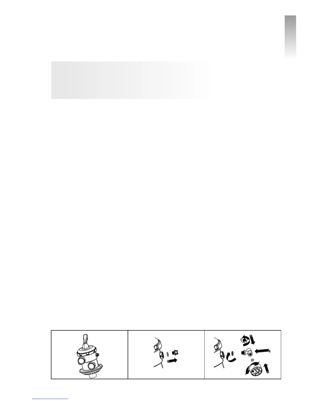
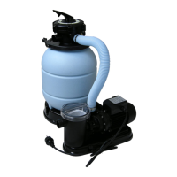
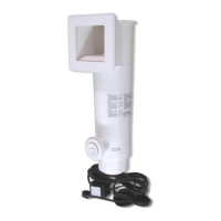
ASSEMBLING THE PRESSURE GAUGE
WITHOUT PRESSURE GAUGE 1 2