11
Energy Recovery Ventilation System
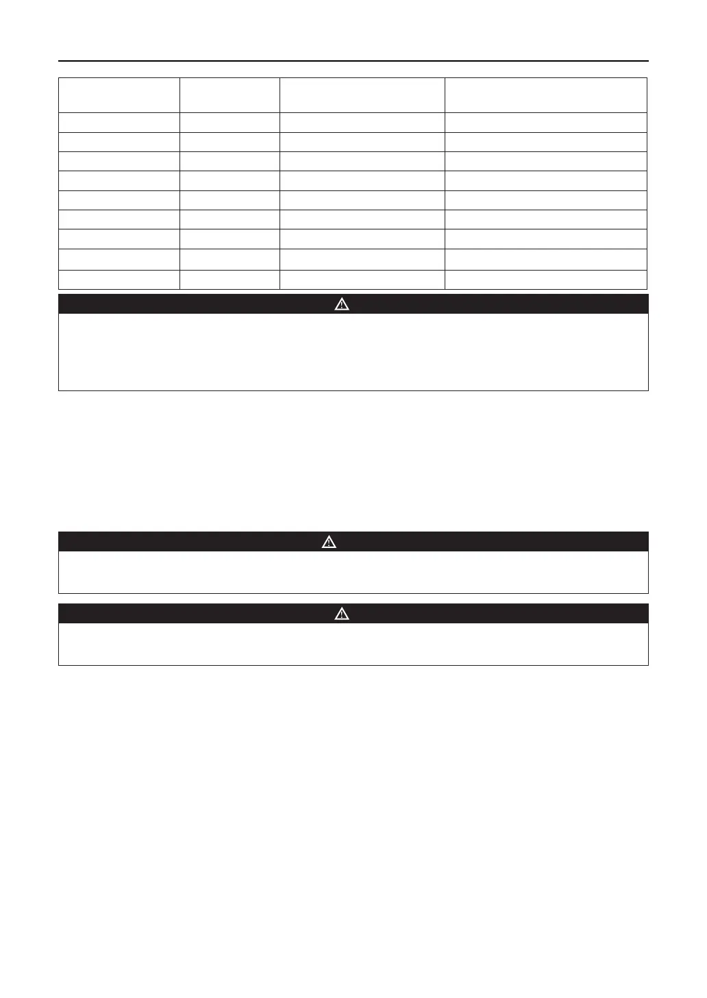
Applied models Power supply Capacity of air switch (A)
Min. sectional area of power
supply line (mm
2
)
FHBQG-D10B-K 220V ~ 50Hz 6 1.0
FHBQG-D13B-K 220V ~ 50Hz 6 1.0
FHBQG-D15B-K 220V ~ 50Hz 6 1.0
FHBQG-D20B-K 220V ~ 50Hz 6 1.0
FHBQG-D25B-M 380V ~ 50Hz 16 2.5
FHBQG-D30B-M 380V ~ 50Hz 16 2.5
FHBQG-D40B-M 380V ~ 50Hz 16 2.5
FHBQG-D50B-M 380V ~ 50Hz 16 2.5
FHBQG-D60B-M 380V ~ 50Hz 16 2.5
NOTE
• The power supply lines for this product must be copper cored cable, and working temperature cannot
exceed the specied value.
• When the power supply lines exceeds 15 meters, please enlarge its sectional area to avoid incidents
caused by overloading.
3.3 Grounding
(1) Reliable grounding measure must be adopted. The yellow green grounding can never be cut o and
xed with tapping screws so as to avoid electrocution.
(2) The grounding resistance should comply with your state or local regulations.
(3) Power supply must be reliably earthed. The ground wire cannot connect to tap water pipe, gas
pipe, drain pipes and other unsecure positions.
WARNING
Cut o the power supply before installation and maintenance to avoid electrocution. Electric wiring
must comply with your state or local electrical codes.
NOTE
GREE is not responsible for adverse results caused by modication of the electric control system by
users themselves without consent of GREE.
4 Commissioning and routine maintenance
Check wirings and perform trial run after installation work.
◆
Check before trial run
(1) Check of the pipeline system
According to design drawing and this manual check layout of ducts, rmness of hangers, anticorrosion
paint and items stated above which should be paid attention to, operation space for replacement of the
air lter, installation location of the duct silencer, inside or top of the duct or equipment, and rmness of
installation.
(2) Check of the electric circuit system
According to the circuit diagram, check the incoming lines, connection method, connections and power
voltage.
 Loading...