Design & Selection
57
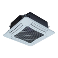
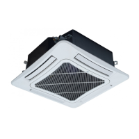
Figure 1 Connection Diagram of the FCU
Step 1: select the unit type based on the air flow, cooling capacity and heating capacity.
a. Select the unit model based on the average cooling load.
b. Select the cooling capacity at the high air flow to meet the average cooling load.
c. Based on the inlet air 27
℃
/DB and 19.5
℃
and entering water temperature 7
℃
, select from the
data sheet get a cooling capacity equal to larger than the cooling load.
d. When the cooling capacity is selected based on the medium or low speed air flow, then at
specific or load peak, use the high-speed for meeting the load demand.
e. For the model selected based on the cooling capacity, when the entering water temperature is
60
℃
, the water flow is the same as that for cooling and the heating capacity can meet the heat
load demand.
f. For the selected FP-85 based on the cooling capacity, the data sheet shows that its sensible
heat cooling capacity is 4160W, the water flow is 0.21L/s, water resistance is 30kPa, and the air
flow is 850m3/h.
g. When the entering water temperature is 60
℃
, the heating capacity is 700W, which meets the
load demand.
Step 2: Check the building noise
a. According to the table in Section 1.2, the allowable noise for the hotel is 40~50dB (A). The
design noise of the FP-85 is 42dBA and 44dBA for the FP-102, both of which can meet the
noise requirement.
Step 3: Select the external static pressure
a. Distribute the air flow for each duct and number them as shown in the figure below
b. Based on the air flow and size of the duct in the figure above, calculate the duct resistance in
accordance with the table below.
 Loading...